


Repair
32 313289S
User Interface/Control Box
NOTE:
This section covers all components included in the wall
power supply control box option and the instrinsically
safe pneumatic power supply control box option.
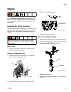
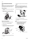
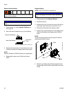
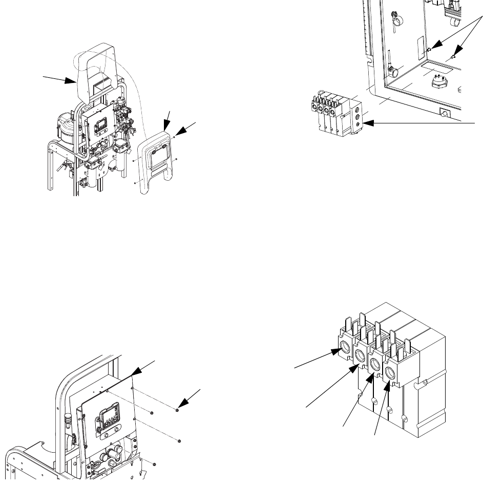
Remove Shroud
1. Close main air shutoff valve on air supply line and
on system.
2. Remove shrouds (12, 13) covering control box.
Remove four nuts (14) and front shroud (12) first.
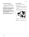
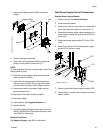
Replace Solenoid Module
Follow this procedure to replace a single solenoid
1. Remove shroud. See Remove Shroud.
2. Disconnect power.
3. Remove four nuts (4); leave two nuts on left side of
panel tight. Open front panel of control box (11).
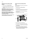
4. Disconnect solenoid cable connectors (242) from
solenoids.
5. Disconnect air tubing from solenoid manifold block
(209).
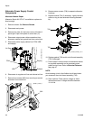
NOTE:
If your sprayer is an intrinsically safe model, you will
need to remove the alternator air regulator from the
solenoid module. See Replace Alternator Regulator,
page 39, for removal instructions.
6. Remove two screws (210).
7. Remove and replace solenoid (209).
8. Reassemble screws (210) and solenoid cable con-
nectors (242).
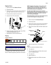
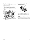
NOTE:
From left to right, solenoid functions are as follows:
• Dosing valve A (DVA) (normally open)
• Dosing valve B (DVB) (normally open)
• Pump A (PA) (normally closed)
• Pump B (PA) (normally closed)
14
13
12
ti21276a
11
4
ti21277a
210
209
r_312359_313289_28
DVA
DVB
PA
PB
r_xm1a00_312359_313289_9_3