


Repair
313289S 37
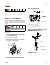
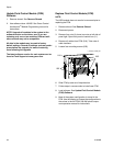
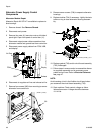
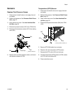
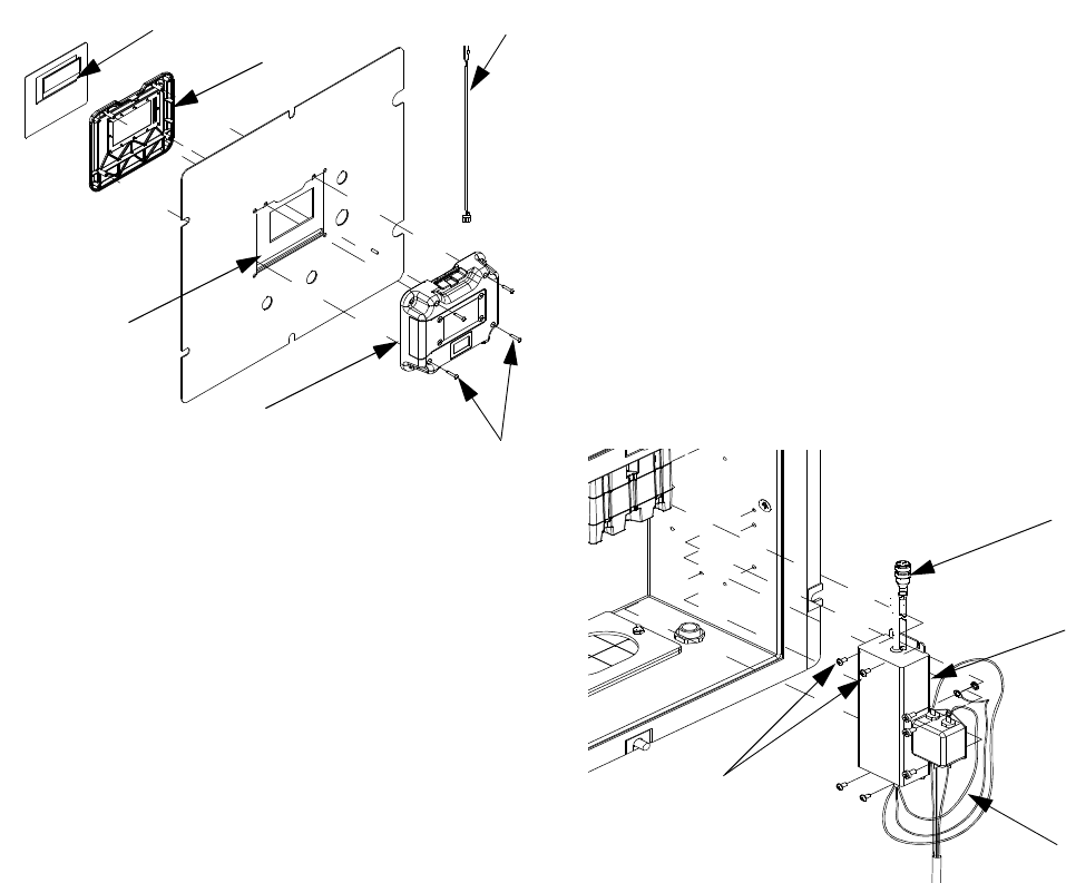
7. Remove front display panel (204d) and gasket
(204g).
8. Discard old display assembly.
9. Place new front display panel (204d) and gasket
(204g) on front panel of control box (11).
NOTE:
To ease installation process use clear tape to hold front
display panel in place.
10. Carefully connect display cables and key switch
cable to new circuit board.
11. Install new rear display panel (204c) and secure
with four screws (204b). Ensure key switch cable
protrudes from opening in top of display module.
12. Install access cover and screws. Apply warning
label to access cover.
13. Reconnect CAN cable to display module.
14. Reconnect power.
15. Load software. See Upgrade Software, 35.
16. Replace shroud.
17. Configure system settings as they were set on old
display. See XM Plural-Component Operation man-
ual 312359 for instructions.
Replace Front Panel
See Replace Display, page 36, for instructions
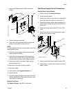
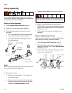
Wall Power Supply Control Components
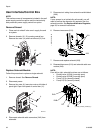
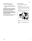
Replace Power Supply Module
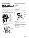
1. Remove shroud. See Remove Shroud.
2. Disconnect main power.
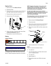
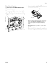
3. Remove four nuts (4); leave two nuts on left side of
panel tight. Open front panel of control box (11).
4. Disconnect incoming power cable connections to
power supply module and ground lead (260) from
control box.
5. Disconnect power supply cable (272) from FCM
(218).
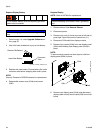
6. Remove four screws (273) holding power supply
module (270) bracket in place.
7. Remove and replace power supply module (270).
8. Follow steps in reverse order to install new power
supply module.
r_xm1a00_312359_313289_25a
204b
204c
204g
204d
Display Cable
239
r_256991_313293_3a-1
272
270
260
273