


Installation
3A0868G 13
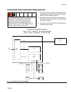
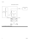
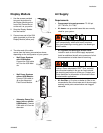
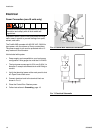
Display Module
1. Use the screws provided
to mount the bracket for
the Display Module on the
front of the Control Box or
on the wall, as you prefer.
2. Snap the Display Module
into the bracket.
3. Connect one end of the CAN
cable (provided) to J6 on the
Display Module (either port).
4. The other end of the cable
comes from the factory connected as shown,
depending on the configuration of your system:
• Wall Power Systems
with USB Module:
Connect the CAN cable
to P3 on the USB Mod-
ule.
• Wall Power Systems
without USB Module:
Connect CAN cable to
J8 on the Advanced
Fluid Control Module.
• Alternator Power Sys-
tems (with or without
USB Module): Connect
CAN cable to J3 on the
alternator.
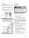
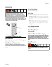
Air Supply
Requirements
• Compressed air supply pressure: 75-100 psi
(517-700 kPa, 5.2-7 bar).
• Air hoses: use grounded hoses that are correctly
sized for your system.
• Air regulator and bleed-type shutoff valve:
include in each air line to fluid supply equipment.
Install an additional shutoff valve upstream of all air
line accessories to isolate them for servicing.
• Air line filter: a 10 micron or better air filter is rec-
ommended to filter oil and water out of the air supply
and help avoid paint contamination and clogged
solenoids.
ti16672a
J6
ti16604a
P3
ti16580a
J8
ti16579a
J3
ti16456a
Trapped air can cause a pump or dispense valve to
cycle unexpectedly, which could result in serious
injury from splashing or moving parts. Use bleed-type
shutoff valves.
If using a Graco electrostatic PRO
™
Gun, a shutoff
valve must be installed in the gun air line to shutoff
the atomizing and turbine air to the gun. Contact your
Graco distributor for information on air shutoff valves
for electrostatic applications.