


Installation
14 3A0868G
Air Connections
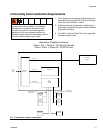
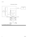
See the System Pneumatic Schematic on page 66
(hazardous location) or page 67 (non-hazardous loca-
tion).
1. Tighten all ProMix 2KE system air and fluid line con-
nections as they may have loosened during ship-
ment.
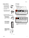
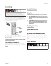
2. Connect the main air supply line to the main air inlet.
This air line supplies the solenoids, valves, and
pumps. See F
IG
. 3.
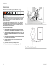
3. For each gun in the system, connect a separate
clean air supply line to the air inlet of the air flow
switch. This air supplies gun atomizing air. The air
flow switch detects air flow to the gun and signals
the controller when the gun is being triggered.
Fluid Supply
Requirements
ProMix 2KE models are available to operate airless
(high pressure, 50 cc pumps only), air spray, or
air-assisted systems with a capacity of up to 3800
cc/min.
• Fluid supply pressure tanks, feed pumps, or circu-
lating systems can be used.
• Materials can be transferred from their original con-
tainers or from a central paint recirculating line.
NOTE: The fluid supply must be free of pressure spikes,
which are commonly caused by pump stroke change-
over. If necessary, install pressure regulators or a surge
tank on the ProMix 2KE fluid inlets to reduce pulsation.
Contact your Graco distributor for additional information.
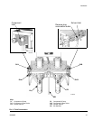
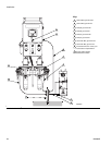
Fluid Connections
1. See F
IG
. 5, page 15. Connect the solvent supply line
to the 1/4 npt(f) solvent valve inlets (SVA and SVB).
2. Connect the component A supply line(s) to the com-
ponent A dose valve inlet (DVA).
NOTE: Paint Recirculating System Only
• If you are recirculating paint, use the standard inlet
on Dose Valve A or Dose Valve B. Remove the plug
directly opposite it on the dose valve for the recircu-
lation outlet. See F
IG
. 5.
3. Connect the component B line to the component B
dose valve inlet (DVB).
4. Connect the gun fluid supply line between the mix
manifold (MM) outlet and the gun fluid inlet.
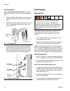
F
IG
. 3. Air Supply Inlet
F
IG
. 4. Connect atomizing air
Main Air
Inlet
ti15708a
Atomizing
air inlets
Atomizing
air outlets
ti15709a
Solenoid
air inlet
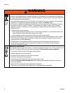
• Do not exceed the pressure rating of the lowest
rated component. See the identification label.
• To reduce the risk of injury, including fluid
injection, you must install a shutoff valve between
each fluid supply line and the mix manifold. Use
the valves to shut off fluid during maintenance
and service.