


Model G0602/G0752 (Mfg. Since 11/12)
-23-
7. Reset the emergency STOP button by twist-
ing it clockwise until it pops out.
To test run your machine:
1. Make sure the spindle direction switch (see
Figure 18) is turned to STOP, and press the
emergency STOP button.
5. Set lathe spindle speed for 150 RPM, (refer
to Setting Spindle Speed on Page 42).
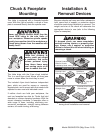
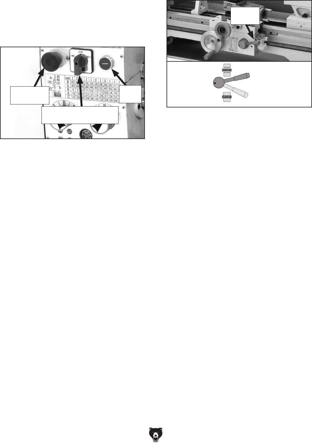
6. Disengage the half nut with the lever shown
in Figure 19.
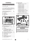
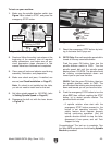
Figure 18. Headstock and gearbox controls.
3. Clear away all tools and objects used during
assembly, lubrication, and preparation.
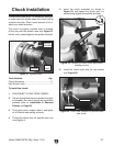
4. Make sure chuck and jaws, if installed, are
secure (see Chuck Installation on Page 27).
Note: If a chuck is not installed on the lathe,
you do not need to install one for this test.
2. Read and follow the safety instructions at the
beginning of the manual, take all required
safety precautions, and make sure all pre-
vious preparation steps discussed in this
manual have been followed and completed.
Emergency
Stop Button
Spindle Direction Switch
Pointing to STOP
8. G0752 Only: Ensure the spindle speed dial is
turned all the way counterclockwise.
Push the green ON button, then turn the
spindle direction switch to FWD. Turn the
spindle speed dial until the spindle speed
display shows 150 RPM. The spindle should
be rotating counterclockwise—down and
toward you as you face the lathe.
G0602: Push the green ON button, then turn
the spindle direction switch to FWD. The
spindle should be rotating counterclockwise—
down and toward you as you face the lathe.
9. Push the emergency STOP button to turn the
lathe OFF, then, without resetting the STOP
button, try to restart spindle rotation. The
spindle should not start.
— If spindle rotation does start with the
emergency STOP button pressed in, the
button is not operating correctly. This
safety feature must operate properly
before continuing operation. Use the
spindle direction switch to stop the lathe,
disconnect it from power, and call Tech
Support for help.
Congratulations! The test run is complete. Turn
the lathe OFF and perform the following Spindle
Break-In procedure.
ON
Button
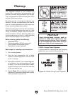
Figure 19. Half nut lever in the disengaged
position.
Engaged
Halfnut
Lever
Disengaged
Half Nut
Lever