


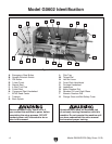
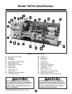
Model G0602/G0752 (Mfg. Since 11/12)
-7-
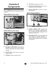
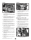
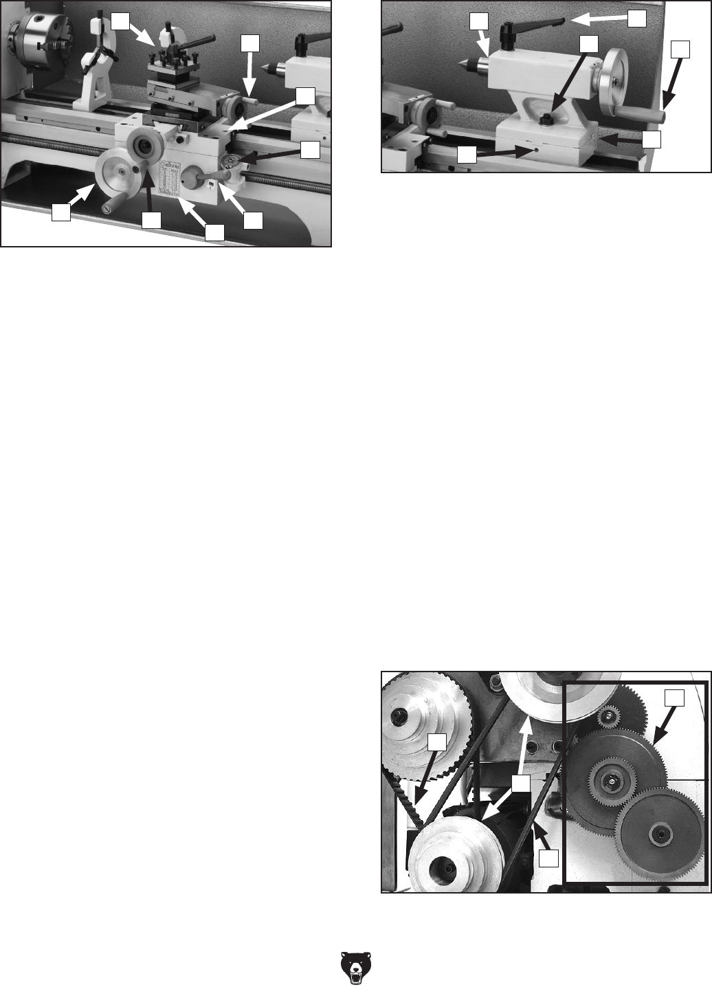
Carriage Tailstock
I. 4-Way Tool Post: Holds up to four cutting
tools at once that can be individually indexed
to the workpiece.
J. Compound Rest Handwheel: Moves the
tool toward and away from the workpiece at
the preset angle of the compound rest.
K. Carriage Lock: Secures the carriage for
greater rigidity when it should not move.
L. Thread Dial: Indicates when to engage the
half nut during threading operations.
M. Half Nut Lever: Engages/disengages half
nut for power feed and threading operations.
N. Thread Chart: Indicates which thread dial
mark to use when engaging the half nut for
specific inch thread pitches.
O. Cross Slide Handwheel: Moves the cross
slide toward and away from the workpiece.
P. Carriage Handwheel: Moves the carriage
along the bedway.
Q. Tailstock Quill: Moves a tool or center
mounted in the tailstock toward or away from
the workpiece.
R. Tailstock Quill Lock Lever: Secures the
quill position.
S. Tailstock Lock Nut: Secures the tailstock to
the bedway.
Figure 6. Carriage controls.
I
L
J
M
O
P
K
N
T. Tailstock Quill Handwheel: Controls the
movement of the quill.
U. Offset Scale: Indicates the relative distance
of tailstock offset from the spindle centerline.
V. Tailstock Offset Set Screw (1 of 2): Adjusts
the tailstock offset left or right from the spin-
dle centerline.
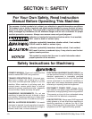
Change Gears, Pulleys, V-Belt
W. Change Gears: The configuration of the
change gears for power feed, inch, and met-
ric threading controls the leadscrew speed.
X. Pulleys: The position of the V-belt on the pul-
leys controls the spindle speed.
Y. V-Belt: Transfers power from the motor pul-
ley to the spindle pulley. Model G0602 uses
two V-belts. Model G0752 uses one V-belt.
Z. Timing-Belt: (G0602) Transfers power from
the motor to the secondary drive pulley.
Figure 7. Tailstock controls.
Q
S
T
U
V
R
Figure 8. Change gears and pulleys
(Model G0602 shown).
X
W
Y
Z