


-28-
Model G0602/G0752 (Mfg. Since 11/12)
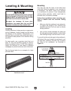
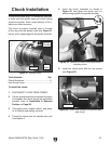
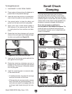
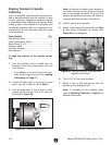
Figure 25. Location to insert chuck keys when
removing chuck.
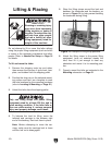
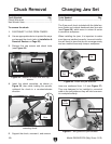
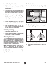
Figure 24. Location of chuck lock and cap
screws.
Chuck Lock
Cap Screw
4. Insert the chuck wrenches, as shown in
Figure 25, then while holding the spindle,
unthread the chuck in a counterclockwise
direction.
5. Support the chuck, unscrew it, and remove.
To remove the chuck:
1. DISCONNECT LATHE FROM POWER!
2. Use an appropriate device to protect the ways
and support the chuck (refer to Installation &
Removal Devices on Page 26).
3. Remove the cap screws and chuck locks
(see Figure 24).
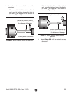
Chuck Removal Changing Jaw Set
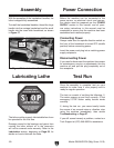
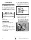
The 3-jaw scroll chuck included with the lathe fea-
tures inside and outside hardened steel jaw sets
(see Figure 26), which move in unison to center
a concentric workpiece.
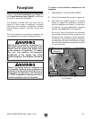
When installing the jaws, it is important to make
sure they are installed correctly. Incorrect installa-
tion will result in jaws that do not converge evenly
and are unable to securely clamp a workpiece.
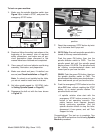
Jaws are numbered from 1–3 (see Figure 27).
They are designed to be installed in numerical
order in the jaw guides so they will hold a concen-
tric workpiece evenly.
Figure 26. Chuck and jaw selection.
Inside
Set
Insert Keys
Here
Tools Needed: Qty
Chuck Wrenches ............................................... 2
Hex Wrench 5mm .............................................. 1
Tools Needed: Qty
Chuck Wrench ................................................... 1
Figure 27. Jaw guide and jaw numbers.
Jaw Numbers
Outside
Set
Jaw
Guides