


Model G0602/G0752 (Mfg. Since 11/12)
-39-
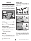
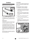
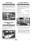
The follow rest mounts to the saddle with two cap
screws (see Figure 47). It is used on long, slender
parts to prevent workpiece deflection from cutting
tool pressure during operation. Adjust the follow
rest fingers in the same manner as the those on
the steady rest.
Note: To reduce the effects of friction, lubricate
the finger tips with generous anti-sieze lubricant
during operation.
Figure 47. Follow rest attachment.
Cap
Screws
Follow Rest
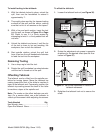
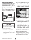
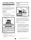
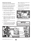
The carriage and cross slide have locks that can
be tightened to provide additional rigidity during
operation, especially during heavy cuts.
See Figure 48 to identify the locations of the
locks for each device.
Carriage & Slide
Locks
Figure 48. Carriage and cross slide locks.
Cross Slide
Lock
Carriage
Lock
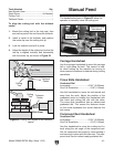
The compound rest handwheel has an indirect-
read graduated scale. This means the distance
shown on the scale represents the actual distance
the tool moves. The base of the compound rest
has another graduated scale used for setting the
cutting tool to a specific angle.
Graduated Dial
Increments ............................... 0.001" (0.025mm)
One Full Revolution ..................... 0.04" (1.02mm)
Tool Needed Qty
Open-End Wrench 14mm .................................. 1
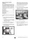
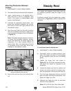
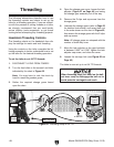
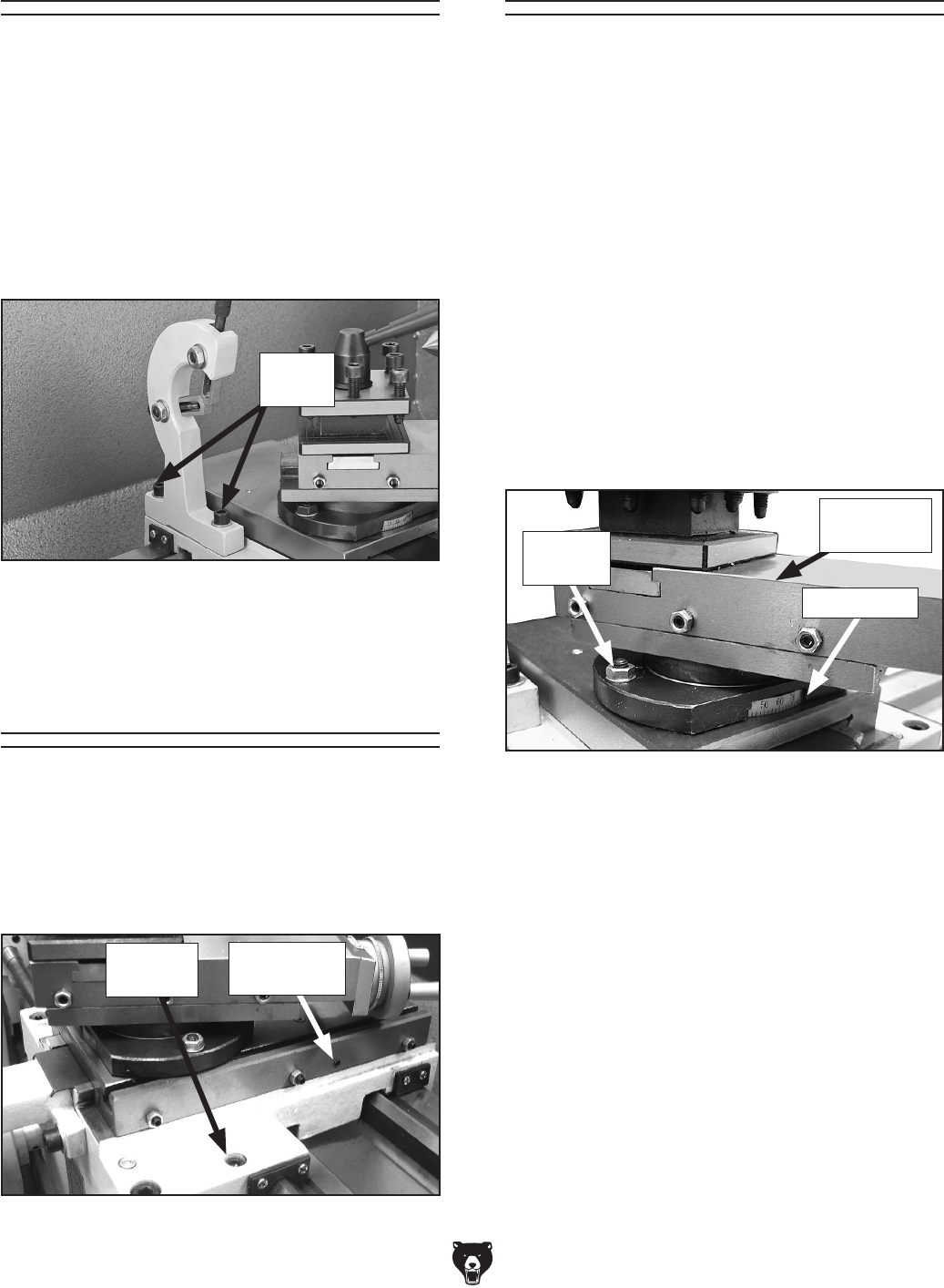
To set the compound rest at a certain angle:
1. Loosen the two hex nuts at the base of the
compound rest (1 of 2 shown in Figure 49).
Compound Rest
2. Rotate the rest to the desired angle, as
indicated by the scale at the base,
then retighten the two hex nuts.
Tip: The first time you set the angle of the
compound rest for cutting threads, mark the
location on the cross slide as a quick refer-
ence point. This will allow you to quickly
return the compound rest to that exact angle
the next time you need to cut threads.
Figure 49. Compound rest.
Compound
Rest
Angle Scale
Hex Nut
(1 of 2)