


Model G0602/G0752 (Mfg. Since 11/12)
-27-
Chuck Installation
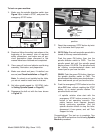
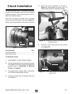
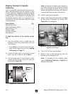
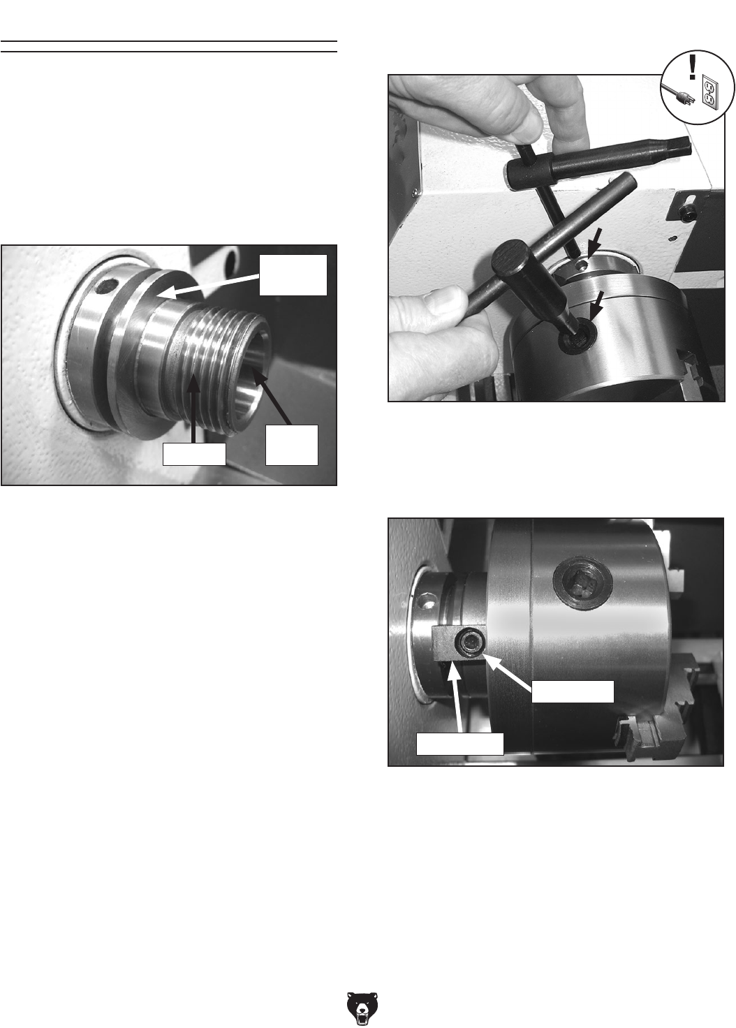
5. Insert the chuck wrenches as shown in
Figure 22, and tighten the chuck until it is
seated snug against the spindle shoulder.
Figure 22. Location to insert chuck keys when
installing chuck.
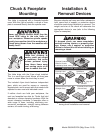
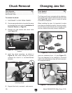
To ensure accurate work, it is extremely important
to make sure the spindle nose and chuck mating
surfaces are clean. Even a small amount of lint or
debris can affect accuracy.
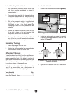
The chuck is properly installed when it threads
all the way onto the spindle nose (see Figure 21
below) and is seated against the spindle shoulder.
6. Install the chuck locks with the cap screws
(see Figure 23).
Figure 23. Chuck lock installed on spindle nose
and chuck.
Chuck Lock
Cap Screw
4. Thread the chuck onto the spindle nose and
hand-tighten it.
3. Thoroughly clean, inspect, deburr, and lightly
oil all threads and mating surfaces.
To install the chuck:
1. DISCONNECT LATHE FROM POWER!
2. Use an appropriate device to protect the ways
and support the chuck during the installation
process (refer to Installation & Removal
Devices on Page 26).
Tools Needed: Qty
Chuck Wrenches ............................................... 2
Hex Wrench 5mm .............................................. 1
Figure 21. Spindle nose.
Threads
Inside
Taper
Spindle
Shoulder