


Model G0602/G0752 (Mfg. Since 11/12)
-33-
To install tooling in the tailstock:
1. With the tailstock locked in place, unlock the
quill, then use the handwheel to extend it
approximately 1".
2. Thoroughly clean and dry the tapered mating
surfaces of the quill and the center, making
sure that no lint or oil remains on the tapers.
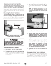
Removing Tooling
1. Use a shop rag to hold the tool.
2. Rotate the quill handwheel counterclockwise
until the tool is forced out of the quill.
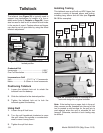
Offsetting Tailstock
The tailstock can be offset from the spindle cen-
terline for turning tapers. Move the tailstock top
casting toward the front of the lathe to machine a
taper at the tailstock end. Conversely, position the
tailstock top casting toward the back of the lathe
to machine a taper at the spindle end.
Note: The marks on the offset indicator are arbi-
trary. For a precise offset, use a dial indicator to
check quill movement while adjusting the screws.
Tools Needed Qty
Hex Wrench 4mm .............................................. 1
Open-End Wrench 19mm .................................. 1
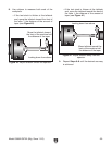
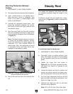
3. With a firm and quick motion, insert the tool
into the quill, as shown in Figure 35 on Page
32. Check to see if it is firmly seated by
attempting to twist it—a firmly seated tool will
not twist.
4. Unlock the tailstock and move it until the tip
of the tool is close to, but not touching, the
workpiece, then re-lock the tailstock.
5. Start spindle rotation, unlock the quill lock
lever, then turn the quill handwheel clockwise
to feed the tool into the workpiece.
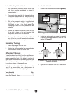
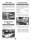
To offset the tailstock:
1. Loosen the tailstock lock nut (see Figure 36).
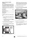
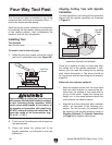
2. Rotate the adjustment set screws in opposite
directions for the desired offset (see the illus-
tration in Figure 37).
Turn
CCW
Turn
CCW
Turn
CW
Turn
CW
Figure 37. Set screw adjustment in relation to
tailstock movement.
3. Retighten the tailstock lock nut to secure the
offset.
Figure 36. Left offset adjustment.
Tailstock
Lock Nut
Adjustment
Set Screw
(1 of 2)
Offset
Indicator