


Model G0602/G0752 (Mfg. Since 11/12)
-41-
Tools Needed Qty
Hex Wrench 6mm .............................................. 1
Steel Shims ....................................... As Needed
Cutting Tool ....................................................... 1
Tailstock Center ................................................. 1
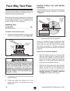
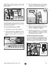
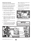
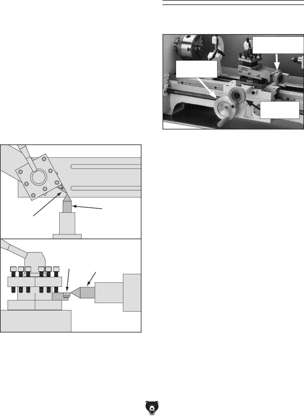
To align the cutting tool with the tailstock
center:
1. Mount the cutting tool in the tool post, then
secure the post so the tool faces the tailstock.
2. Install a center in the tailstock, and position
the center tip near the cutting tool tip.
3. Lock the tailstock and quill in place.
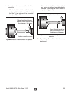
4. Adjust the height of the cutting tool so that the
tool tip is aligned vertically and horizontally
with the center tip, as shown in Figure 52.
Cutting
Tool
Tailstock
Center
(Side View)
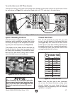
Figure 52. Cutting tool aligned to the tailstock
center.
Cutting
Tool
Tailstock
Center
(Top View)
Carriage Handwheel
Use the carriage handwheel to move the carriage
left or right along the bed. This control is help-
ful when setting up the machine for turning or
when manual movement is desired during turning
operations.
Cross Slide Handwheel
Graduated Dial
Increments ............................... 0.001" (0.025mm)
One Full Revolution ..................... 0.06" (1.52mm)
Use this handwheel to move the tool toward and
away from the work. Adjust the position of the
graduated scale by holding the handwheel with
one hand and turning the dial with the other.
The cross slide handwheel has an indirect-read
graduated dial. This means the distance shown
on the scale represents the actual distance the
tool moves.
Compound Rest Handwheel
Graduated Dial
Increments .............................. 0.001" (0.025mm)
One Full Revolution ..................... 0.04" (1.02mm)
Use this handwheel to move the cutting tool lin-
early along the set angle of the compound rest.
Set the compound rest angle by hand-rotating it
and securing in place with two hex nuts. The com-
pound rest has an indirect-read graduated dial.
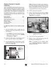
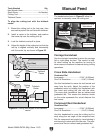
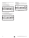
The handwheels shown in Figure 53 allow the
operator to manually move the cutting tool.
Manual Feed
Figure 53. Manual handwheel controls.
Carriage
Handwheel
Cross Slide
Handwheel
Compound Rest
Handwheel