


-32-
Model G0768/G0769 (Mfd. Since 8/15)
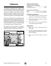
Chuck & Faceplate
Mounting
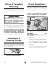
This lathe ships with the 3-jaw chuck installed.
This is a scroll-type chuck where all three jaws
move in unison when the chuck key is used.
The included 4-jaw chuck features independent
jaws, which are used for square or unevenly-
shaped stock, and to mount work that needs to be
adjusted to near zero total indicated runout.
The included faceplate has slots for T-bolts that
hold standard or custom clamping hardware. With
the correct clamping hardware, a faceplate offers
a wide range of uses, including machining non-
concentric workpieces, straight turning between
centers, off-center turning, and boring.
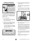
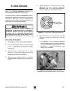
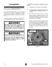
Never use spindle speeds faster than chuck
RPM rating or safe limits of your workpiece.
Excessive spindle speeds greatly increase
risk of workpiece or chuck being thrown
from machine with deadly force!
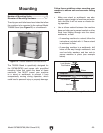
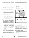
This lathe is equipped with an intrinsic backplate
spindle nose. With this type of spindle, a chuck or
faceplate is mounted directly to the backplate with
hex nuts.
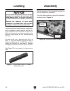
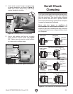
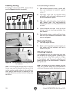
Installation &
Removal Device
Figure 23. Example of common device used
during chuck installation and removal.
Plywood Protection
Plate for Chucks
Installed by Hand
Place a piece of plywood over the bedways to pro-
tect them from damage if a chuck or other tooling
is dropped (see below).
Chuck Installation
To ensure accurate work, it is extremely important
to make sure the spindle nose and chuck mating
surfaces are clean. Even a small amount of lint or
debris can affect accuracy.
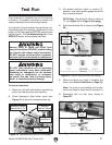
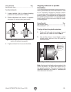
The chuck is properly installed when it is seated
against the backplate shoulder (see Figure 24).
Tools Needed: Qty
Open-End Wrench 13mm .................................. 1
Lathe Chuck Key ............................................... 1
To install chuck:
1. DISCONNECT MACHINE FROM POWER!
2. Use an appropriate device to protect ways
(refer to Installation & Removal Device
subsection).
3. Thoroughly clean and wipe down all mating
surfaces with a lightly-oiled, lint-free rag.
Figure 24. Spindle backplate parts.
Inside
Taper
Mounting
Hole
Shoulder