


-44-
Model G0768/G0769 (Mfd. Since 8/15)
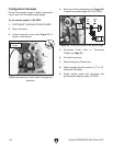
2. Rotate rest to desired angle, as indicated by
scale at base, then retighten cap screws.
Tip: The first time you set the compound rest
angle for cutting threads, mark the location
on the cross slide as a quick reference point.
This will allow you to quickly return the com-
pound rest to that exact angle the next time
you need to cut threads.
The compound rest handwheel has an indirect-
read graduated scale. This means that the dis-
tance shown on the scale represents the actual
distance the cutting tool moves. The base of the
compound rest has another graduated scale used
for setting the cutting tool to a specific angle.
Graduated Dial
Increments ............................... 0.001" (0.025mm)
One Full Revolution ..................... 0.05" (1.27mm)
Tool Needed Qty
Hex Wrench 4mm .............................................. 1
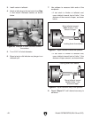
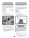
To set compound rest angle:
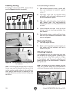
1. Loosen cap screws shown in Figure 49.
Compound Rest Four-Way Tool Post
Tool Needed Qty
Tool Post T-Wrench ........................................... 1
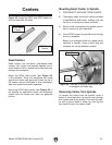
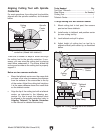
Installing Tool
The four-way tool post is mounted on top of the
compound rest
and allows a maximum of four
tools
to be loaded simultaneously.
Each tool can be quickly indexed to the workpiece
by
loosening the top handle, rotating the tool
post to the desired position, then retightening the
handle to lock the tool into position.
To install tool in tool post:
1
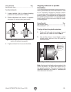
. Adjust tool post bolts so cutting tool can fit
underneath them (see below).
Figure 50. Example of tool mounted in tool post.
Cutting
Tool
Tool Post
Bolt
2. Firmly secure cutting tool with at least two
tool post bolts.
3.
Check and adjust cutting tool to spindle cen-
terline, as instructed in next subsection.
Over-extending a cutting tool from the post
will increase risk of tool chatter, breakage,
or tool loosening during operation, which
could cause metal pieces to be thrown at
the operator or bystanders with great force.
DO NOT extend a cutting tool more than 2.5
times the width of its cross-section (e.g.,
2.5 x 0.5" = 1.25").
Figure 49. Compound rest angle adjustments.
Cap
Screws
Angle
Scale