


Model G0768/G0769 (Mfd. Since 8/15)
-51-
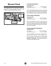
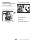
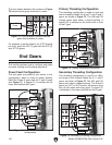
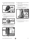
Because there is only one spacer, on some
setups smaller gears must be used as spac-
ers on the adjustable gears.
Both positions must be filled for the gears to work
properly. This also applies to the "blank" areas on
the chart, such as the one left of the 50T (F) gear
shown in Figure 69. A spacer should be installed
in this position on the shaft. A spacer is not listed
because chart only reflects ACTIVE gear posi-
tions.
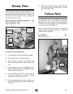
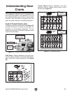
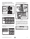
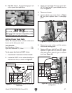
Figure 68 identifies the end gears on the upper,
middle, and lower shafts. The gears are repre-
sented by letters.
Upper Shaft Gears
Figure 68. Identification of gears on shafts.
A
C D
B
E F
A
C D
B
E F
30
19 20 22 24
32 40 44
80 80
30 33 40
65 70 80 60
6060 60 63
63
53
9 10 11 12
13 14 16
18
50 50 55
80
80
80 80 80
80 60
60
71 53 55
33 3055 554030
53 53 53
72 63 70
57 57
72 72
7272 80 70
40 40 40
63 57
55
Lower Shaft Gears
Middle Shaft Gears
Upper Shaft Gears
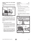
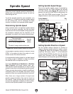
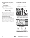
The shaded boxes in Figure 67 show the threads
per inch (TPI) on the applicable chart.
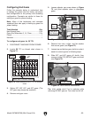
Each shaft has room to mount gears in two posi-
tions—forward and rear (see Figure 69).
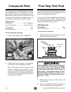
Figure 66 identifies the charts to use when set-
ting carriage feed movement for metric or inch
threading.
mm
n/1"
A
C D
B
E F
A
C D
B
E F
0.40
1.25 1.50 1.75 2.00 2.50 3.00
55
80
80
53
71 7163
57
71 7163 33 3060 40 40
506084805060
20
80 80
80 63 63
80
60 70
70
70
57 72 80
80
30 33 5330 6040 40 4030 3370
0.50 0.60 0.70 0.80 1.00
A
CD
B
E F
A
CD
B
E F
30
19 20 22 24 32 40 44
80 80
30 33 40 65 70 80 60
6060 60 63
63
53
9 10 11 12 13 14 16
18
50 50 55
80
80 80 80 80
8060
60
7153 55 33 3055 554030
53 53 53 72 63 70
57 57 72 72
7272 80 70 40 40 40
63 5755
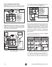
Figure 66. Icons indicate inch or metric threads.
How to Read the Thread Charts
Inch Icon
Indicating
Threads per
Inch (TPI)
Metric Icon
Indicating
Thread Pitch
A
C D
B
E F
A
C D
B
E F
30
19 20 22 24 32 40 44
80 80
30 33 40 65 70 80 60
6060 60 63
63
53
9 10 11 12 13 14 16
18
50 50 55
80
80 80 80 80
80 60
60
71 53 55 33 3055 554030
53 53 53 72 63 70
57 57 72 72
7272 80 70 40 40 40
63 5755
Figure 67. Numbers in shaded boxes indicate
the TPI or threads per inch.
Threads
Per Inch
(TPI)
Forward
Gears
Rear
Gears
Spacer
A
C D
B
E F
A
C D
B
E F
30
19 20 22 24 32 40 44
80 80
30 33 40 65 70 80 60
6060 60 63
63
53
9 10 11 12 13 14 16
18
50 50 55
80
80 80 80 80
80 60
60
71 53 55 33 3055 554030
53 53 53 72 63 70
57 57 72 72
7272 80 70 40 40 40
63 5755
Figure 69. Identification of forward and rear gear
positions.
Forward
Blank Area Indicates
Spacer (Not Shown)
Rear