


-50-
Model G0768/G0769 (Mfd. Since 8/15)
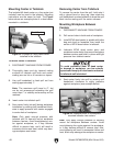
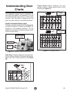
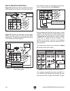
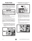
Figure 62 identifies the three available feed rates
and the feed icon at the top of the feed rate chart.
How to Read the Feed Chart
0.0071"
0.0037"
84
20
A
A
40
in/
C
C
D
D
B
B
E
E
F
F
80 80
80
30 72
33 80
30
0.0068"
Figure 62. Chart displays the three feed rates.
Feed Rates
Feed Rate
Icon
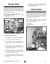
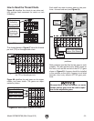
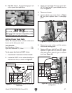
Both positions must be filled for the gears to work
properly. This also applies to "blank" areas on the
chart, such as the one right of the 80T (E) gear
in Figure 64 (the dashed box is used for identifi-
cation only). A spacer should be installed in this
position on the shaft. A spacer is not listed on
the chart because the chart only reflects ACTIVE
gear positions.
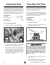
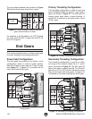
The lines shown between the numbers in Figure
65 identify which gears mesh.
Each shaft has room to mount gears in two posi-
tions—forward and rear (see Figure 64).
0.0071"
0.0037"
84
20
A
A
40
in/
C
C
D
D
B
B
E
E
F
F
80 80
80
30 72
33 80
30
0.0068"
Figure 64. Forward and rear gear positions.
Forward
Rear
Blank Area Indicates
Spacer (Not Shown)
0.0071"
0.0037"
84
20
A
A
40
in/
C
C
D
D
B
B
E
E
F
F
80 80
80
30 72
33 80
30
0.0068"
Figure 65. Lines indicate which gears mesh.
Gear Mesh
Lines
For example, to set the feed rate for 0.0037 in./
rev., mesh the 30T (B) gear with the 80T (D) gear,
and mesh the 20T (C) gear with the 80T (E) gear.
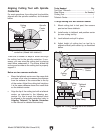
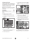
Figure 63 identifies the end gears on the upper,
middle, and lower shafts, and the 40-tooth (40T)
spindle gear. The gears are represented by letters
in the columns and the diagram.
0.0071"
0.0037"
84
20
A
A
40
in/
C
C
D
D
B
B
E
E
F
F
80 80
80
30 72
33 80
30
0.0068"
Figure 63. Identification of upper, middle and
lower shaft gears.
Upper
Shaft
Gears
Lower Shaft Gears
Middle Shaft Gears
Spindle
Gear
Columns