


Model G0768/G0769 (Mfd. Since 8/15)
-81-
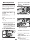
Tensioning &
Replacing V-Belts
V-belts stretch and wear with use, so it is impor-
tant to routinely monitor belt tension. V-belts that
are improperly tensioned or exposed to grease/oil
will slip and poorly transmit power from the motor.
To ensure optimal power transmission, inspect
belts on a monthly basis to verify they are properly
tensioned and free of oil/grease. Replace V-belts
when they become cracked, frayed, or glazed.
Tools Needed Qty
Hex Wrench 3, 4mm ....................................1 Ea.
Open-End Wrench 10, 13 mm .....................1 Ea.
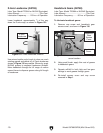
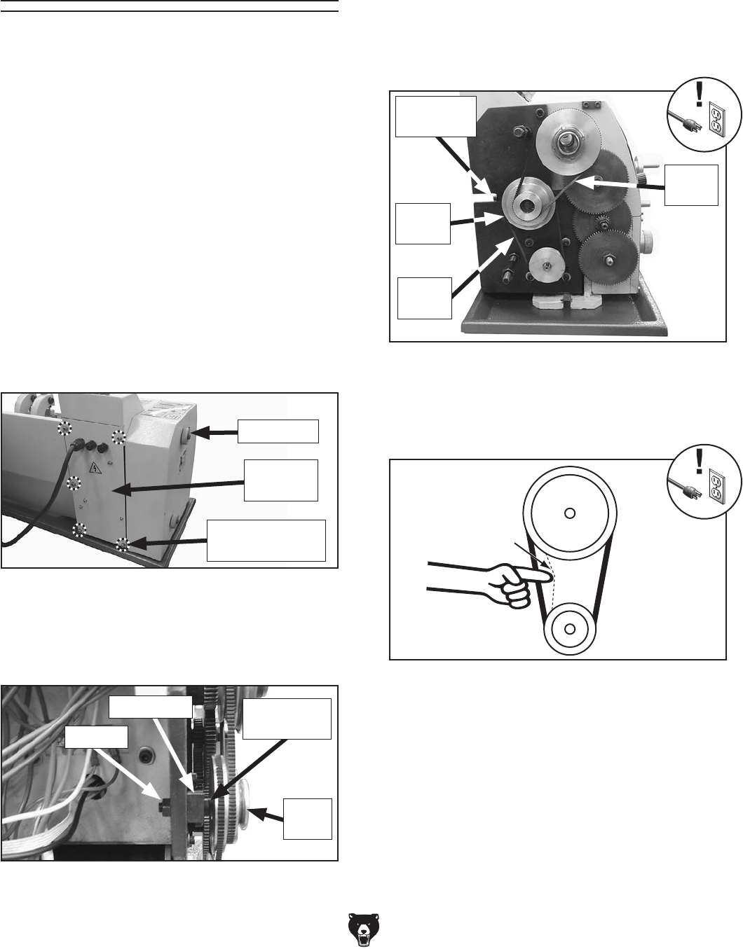
Pulley
Deflection
Pulley
Figure 140. Correct V-belt deflection.
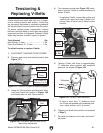
1
⁄8"
5. Tension V-belts until there is approximately
1
⁄8" deflection when pushed with moderate
pressure, as shown in Figure 140.
—If there is more than
1
⁄8" deflection when
the V-belts are pushed with moderate pres-
sure, adjust tension until it is correct.
6. Tighten pivot block bolt and hex nut loosened
in Step 3.
7. Re-install and secure end cover and electri-
cal panel.
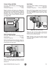
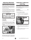
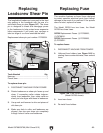
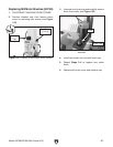
Figure 139. Tensioner screw and V-belts.
Upper
V-Belt
Tensioner
Screw
Idler
Pulley
4. Turn tensioner screw (see Figure 139) clock-
wise to tension V-belts or counterclockwise to
loosen V-belts.
—If replacing V-belts, loosen idler pulley and
carefully roll upper and lower V-belts off of
pulleys, then re-install new V-belts in same
manner.
Lower
V-Belt
To adjust tension or replace V-belts:
1. DISCONNECT MACHINE FROM POWER!
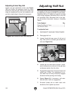
2. Remove end cover and electrical panel (see
Figure 137).
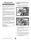
3. Using flat 10mm wrench provided with lathe,
hold pivot block bolt shown in Figure 138,
and loosen hex nut with 13mm wrench.
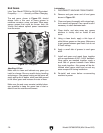
Figure 138. Pivot block bolt and hex nut for
idler pulley adjustment.
Hex Nut
Pivot Block
Bolt
Pivot Block
Idler
Pulley
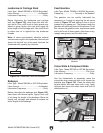
Figure 137. Location of parts for removing panel.
Electrical
Panel
End Cover
Cap Screws to
Remove (1 of 5)