


-6-
Model G0768/G0769 (Mfd. Since 8/15)
Controls &
Components
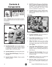
Refer to Figures 3–8 and the following descrip-
tions to become familiar with the basic controls of
this machine.
To reduce your risk of
serious injury, read this
entire manual BEFORE
using machine.
Headstock
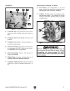
F. Lathe/Mill Selector Switch (G0769 Only):
Used to select between lathe mode (1), or
mill mode (2).
A. Feed Direction Dial: Used to select direction
of leadscrew rotation when spindle is rotating
in downward (F) direction. Used to switch
between right or left thread cutting.
B. Spindle Speed Dial: Controls spindle speed.
C. Spindle Speed RPM Display: Shows spin-
dle speed.
D. Spindle Direction Switch: Selects spindle
rotation direction.
Figure 3. Control panel.
E
F
B
C
D
A
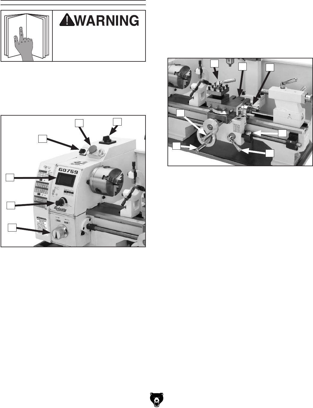
Carriage
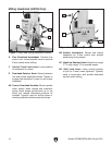
G. Carriage Handwheel: Manually moves car-
riage left or right along bedway.
H. Cross Slide Handwheel: Moves cross slide
toward and away from workpiece.
I. 4-Way Tool Post: Holds up to four cutting
tools at once that can be individually indexed
to workpiece and quickly moved into position
when needed.
J. Cross Slide Table (G0769 Only): Supports
workpieces for milling/drilling operations.
Includes T-slots for mounting milling vises or
other fixtures.
K. Compound Rest Handwheel: Moves tool
toward and away from workpiece at preset
compound angle.
L. Thread Dial: Indicates when to engage the
half nut during threading operations.
M. Half Nut Lever: Engages/disengages half
nut for power feeding and threading opera-
tions.
Figure 4. Carriage controls.
I
K
L
M
G
H
J
E. ON/OFF Switch w/Emergency Stop Button:
When pressed, cuts power to motor and con-
trol panel. To reset, press front tab, lift switch
cover, and press green ON button. Cover
must be unlatched for machine to run.