


Model G0768/G0769 (Mfd. Since 8/15)
-57-
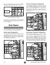
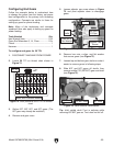
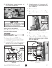
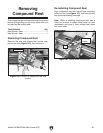
To avoid potential carriage/chuck crash,
disengage half nut lever immediately after
completing power feed operations.
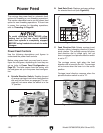
D. Half Nut Lever: Engages/disengages half
nut for power feed operations.
Figure 90. Half nut lever.
D
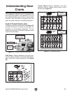
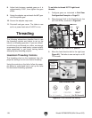
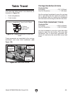
3. Gather the required A–F change gears: 84T,
30T, 20T and two 80T gears, based upon the
chart in Figure 91.
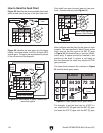
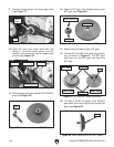
4. Remove end cover.
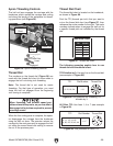
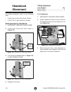
5. Loosen adjuster cap screw shown in Figure
92, and pivot adjuster down to disengage
gears.
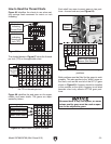
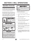
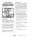
6. Remove hex nuts, e-clips, and flat washers
that secure existing gears.
7. Replace A/B gear with 84T and 30T gears,
replace C/D gear with 20T and 80T gears,
and install spacer with 80T gear on bottom
shaft (see Figure 93).
Figure 92. Adjustor cap screw location.
Adjustor Cap
Screw
Follow the example below to better understand
how to set the lathe power feed.
Tools Needed:
Hex Wrenches 4, 5mm .................................1 Ea
Open-End Wrenches 13, 14mm ...................1 Ea
To set power feed rate to 0.0037 in/rev.:
1. DISCONNECT MACHINE FROM POWER!
2. Locate the 0.0037 in./rev. column heading on
the feed rate chart, as shown in Figure 91.
Setting Power Feed Rate
Figure 91. Change gears for 0.0037 in./rev. on
feed chart.
0.0071"
0.0037"
84
20
A
A
40
in/
mm
n/1"
C
C
D
D
B
B
E
E
F
A
C D
B
E F
A
C D
B
E F
F
80 80
0.40
1.25 1.50 1.75 2.00 2.50 3.00
55
80
80
53
71 71 63
57
71 7163 33 30 60 40 40
506084805060
20
80 80
80 63 63
80
60 70
70
70
57 72 80
80
30 33 53 30 60 40 40 4030 3370
0.50 0.60 0.70 0.80 1.00
80
30 72
33 80
30
0.0068"
A
C D
B
E F
A
C D
B
E F
30
19 20 22 24 32 40 44
80 80
30 33 40 65 70 80 60
6060 60 63
63
53
9 10 11 12 13 14 16
18
50 50 55
80
80 80 80 80
80 60
60
71 53 55 33 3055 554030
53 53 53 72 63 70
57 57 72 72
7272 80 70 40 40 40
63 5755
0.0037 in./rev.
Change
Gears
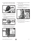
Figure 93. Power feed change gear
configuration.
0.0071"
0.0037"
84
20
A
A
40
C
C
D
D
B
B
E
E
F
F
80
80
80
30
72
33 80
30
0.0068"
E Gear
F (Spacer)
D Gear
C Gear
B Gear
A Gear