


Model G0768/G0769 (Mfd. Since 8/15)
-47-
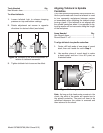
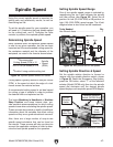
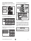
Setting Spindle Direction & Speed
Set the spindle rotation direction to forward or
reverse with the spindle direction switch, shown
in Figure 56. Reset the Emergency Stop button,
press the ON button, select "1" on the lathe/mill
selector (Model G0769 only) then turn the spindle
speed dial clockwise until the desired spindle
speed displays on the spindle speed RPM display.
Spindle Speed
Using the correct spindle speed is important for
getting
safe and satisfactory results, as well as
maximizing tool life.
To set the spindle speed for your operation, you
will need to: 1) Determine the
best
spindle speed
for the cutting task, and 2)
Configure the
lathe
controls to produce the required spindle speed.
Cutting Speed (FPM) x 12
*Recommended
Dia. of Cut (in inches) x 3.14
Spindle
Speed
(RPM)
*Double if using carbide cutting tool
=
Figure 54. Spindle speed formula for lathes.
Determining Spindle Speed
Many variables affect the optimum spindle speed
to use for any given operation
, but the two most
important are the recommended cutting speed for
the workpiece material and the diameter of the
workpiece, as noted in the formula shown below.
Cutting speed, typically defined in feet per minute
(FPM), is the speed at which the edge of a tool
moves across the material surface.
A recommended cutting speed is an ideal speed
for cutting a
type of material in order to produce
the desired finish and optimize tool life.
The books
Machinery’s Handbook or
Machine
Shop Practice
, and some internet sites, pro-
vide excellent recommendations for which cutting
speeds to use when calculating the spindle speed.
The
se sources
also provide a wealth of additional
information about the variables that affect cutting
speed and
they are a good educational resource.
A
lso, there are a large number of easy-to-use
spindle speed calculators that can be found on
the internet.
These sources will help you
take into
account the applicable variables in order to deter-
mine the best spindle speed for the operation.
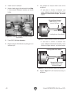
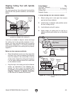
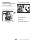
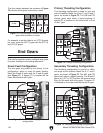
Setting Spindle Speed Range
One of two spindle speed ranges is selected by
repositioning the top V-belt between the spindle
and idler pulleys (see Figure 55). Select the A
position for low (50-1000 RPM) or B position for
high (100 –2000 RPM) speed ranges. The V-belt
diagram below is also found on the headstock.
Tools Needed Qty
Hex Wrench 4mm .............................................. 1
Figure 55. Belt positioned for low speed.
A
B
M
Low
High
Spindle
Pulley
Motor
Pulley
Idler
Pulley
Top
V-Belt
Figure 56. Spindle speed and direction controls.
Spindle
Direction
Switch
Lathe/Mill Selector
Switch (G0769 Only)
Emergency
Stop
Button
Spindle
Speed RPM
Display
Spindle
Speed Dial