


-52-
Model G0768/G0769 (Mfd. Since 6/14)
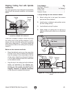
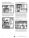
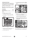
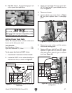
Primary Threading Configuration
This threading configuration is used for inch and
metric threading. Mesh the A and C, and D and F
gears, as shown in Figure 72. The A/B and C/D
change gears each share a keyed bushing. A
spacer (E) is installed on the lower shaft in front
of the F gear.
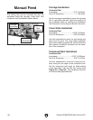
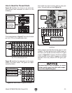
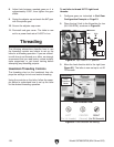
Secondary Threading Configuration
This threading configuration is used for a differ-
ent range of inch threads. Mesh the A, C, and E
gears, as shown in Figure 73. The A/B, and C/D
gears each share a keyed bushing. The B and D
gears (e.g. 20T or 30T) function as spacers since
they do not mesh with other gears. A spacer (F)
is installed on the lower shaft behind the E gear.
Figure 73. Secondary threading configuration.
A
C D
B
E F
A
C D
B
E F
30
19 20 22 24 32 40 44
80
80
30 33 40 65 70 80 60
6060 60 63
63
53
9
10 11 12 13 14 16
18
50 50 55
80
80 80 80 80
80 60
60
71 53 55 33 3055 5540 30
53 53 53 72 63 70
57 57 72 72
7272 80 70 40 40 40
63 5755
E Gear
A Gear
B Gear
C Gear
D Gear
F (Spacer)
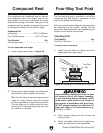
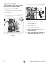
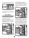
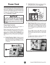
This section explains how to configure end gears
for power feeding and threading operations.
End Gears
Power Feed Configuration
The end gears are preset by the factory in this
configuration, which is used for power feeding.
Mesh the B and D gears and the C and E gears
(see Figure 71). A spacer (F) is installed on the
lower shaft behind the E gear.
Figure 71. Power feed change gear
configuration.
0.0071"
0.0037"
84
20
A
A
40
C
C
D
D
B
B
E
E
F
F
80
80
80
30
72
33 80
30
0.0068"
E Gear
F (Spacer)
D Gear
C Gear
B Gear
A Gear
Figure 72. Primary threading configuration.
A
C D
B
E F
A
C D
B
E F
30
19
20 22 24 32 40 44
80 80
30 33 40 65 70 80 60
6060 60 63
63
53
9 10 11 12 13 14 16
18
50
50 55
80
80 80 80 80
80 60
60
71 53 55 33 3055 5540 30
53
53 53 72 63 70
57 57 72 72
7272 80 70 40 40 40
63 5755
A Gear
E (Spacer)
F Gear
B Gear
C Gear
D Gear
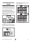
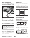
The lines shown between the numbers in Figure
70 indicate which gears should be in mesh.
A
C D
B
E F
A
C D
B
E F
30
19 20 22 24 32 40 44
80 80
30
33 40 65 70 80 60
6060 60 63
63
53
9 10 11 12 13 14 16
18
50 50 55
80
80 80 80 80
80 60
60
71 53 55 33 3055 5540 30
53 53 53 72 63 70
57
57 72 72
72
72 80
70 40 40 40
63 57
55
Figure 70. Lines between numbers indicate
gears that should be in mesh.
Gear Mesh
Lines
For example, to set the lathe to cut 9 TPI (threads
per inch), mesh the 80T (C) gear with the 53T (A)
and 30T (E) gears.