


1 - 12
Default
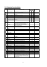
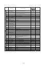
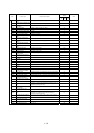
Code Function name Monitored data or setting
_FF _FEF _FUF
Note
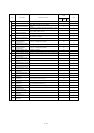
C038
Low-current indication signal
output mode selection
00 (output during acceleration/deceleration and constant-speed operation),
01 (output only during constant-speed operation)
01
C039
Low-current indication signal
detection level
0.0 to 2.00 x "rated current" (A)
Rated current of
inverter
C040 Overload signal output mode
00 (output during acceleration/deceleration and constant-speed operation),
01 (output only during constant-speed operation)
01
C041 Overload level setting 0.0 to 2.00 x "rated current" (A)
Rated current of
inverter
C042 Frequency arrival setting for accel. 0.00 to 99.99, 100.0 to 400.0 (Hz) 0.00
C043 Frequency arrival setting for decel. 0.00 to 99.99, 100.0 to 400.0 (Hz) 0.00
C044 PID deviation level setting 0.0 to 100.0 (%) 3.0
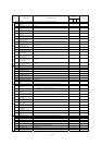
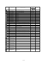
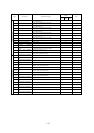
C045
Frequency arrival setting for
acceleration (2)
0.00 to 99.99, 100.0 to 400.0 (Hz) 0.00
C046
Frequency arrival setting for
deceleration (2)
0.00 to 99.99, 100.0 to 400.0 (Hz) 0.00
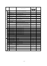
C052 Maximum PID feedback data 0.0 to 100.0 (%) 100.0
C053 Minimum PID feedback data 0.0 to 100.0 (%) 0.0
C055
Over-torque (forward-driving) level
setting
0. to 200. (%) 100.
C056
Over-torque (reverse
regenerating) level setting
0. to 200. (%) 100.
C057
Over-torque (reverse driving) level
setting
0. to 200. (%) 100.
C058
Over-torque (forward
regenerating) level setting
0. to 200. (%) 100.
C061
Electronic thermal warning level
setting
0. to 100. (%) 80.
C062 Alarm code output 00 (disabling), 01 (3 bits), 02 (4 bits) 00
C063 Zero speed detection level 0.00 to 99.99, 100.0 (Hz) 0.00
Levels and output terminal status
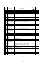
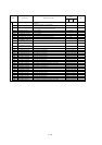
C064 Heat sink overheat warning level
0. to 200.0 (°C)
120.
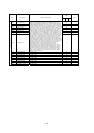
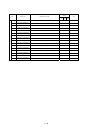
C071 Communication speed selection
02 (loopback test), 03 (2,400 bps), 04 (4,800 bps), 05 (9,600 bps), 06
(19,200 bps)
04
C072 Node allocation 1. to 32. 1.
C073
Communication data length
selection
7 (7 bits), 8 (8 bits) 7
C074 Communication parity selection 00 (no parity), 01 (even parity), 02 (odd parity) 00
C075 Communication stop bit selection 1 (1 bit), 2 (2 bits) 1
C076
Selection of the operation after
communication error
00 (tripping), 01 (tripping after decelerating and stopping the motor), 02
(ignoring errors), 03 (stopping the motor after free-running), 04
(decelerating and stopping the motor)
02
C077
Communication timeout limit
before tripping
0.00 to 99.99 (s) 0.00
C078 Communication wait time 0. to 1000. (ms) 0.
Communication function
C079 Communication mode selection 00(ASCII), 01(Modbus-RTU) 00
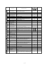
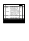
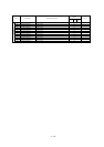
C081 [O] input span calibration 0. to 9999., 1000 to 6553(10000 to 65530) Factory setting
C082 [OI] input span calibration 0. to 9999., 1000 to 6553(10000 to 65530) Factory setting
C083 [O2] input span calibration 0. to 9999., 1000 to 6553(10000 to 65530) Factory setting
C085 Thermistor input tuning 0.0 to 999.9, 1000. Factory setting
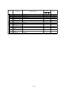
Adjustment
C091 Debug mode enable (Do not change this parameter, which is intended for factory adjustment.) 00
C101 Up/Down memory mode selection 00 (not storing the frequency data), 01 (storing the frequency data) 00
C102 Reset mode selection
00 (resetting the trip when RS is on), 01 (resetting the trip when RS is off), 2
(enabling resetting only upon tripping [resetting when RS is on])
00
Others
C103 Restart mode after reset
00 (starting with 0 Hz), 01 (starting with matching frequency), 02 (restarting
with active matching frequency),03(resetting only trip)
00
C105 FM gain adjustment 50. to 200. (%) 100.
C106 AM gain adjustment 50. to 200. (%) 100.
C107 AMI gain adjustment 50. to 200. (%) 100.
C109 AM bias adjustment 0. to 100. (%) 0.
Meter
adjustment
C110 AMI bias adjustment 0. to 100. (%) 20.