2 - 5
2.2 Option boards error codes
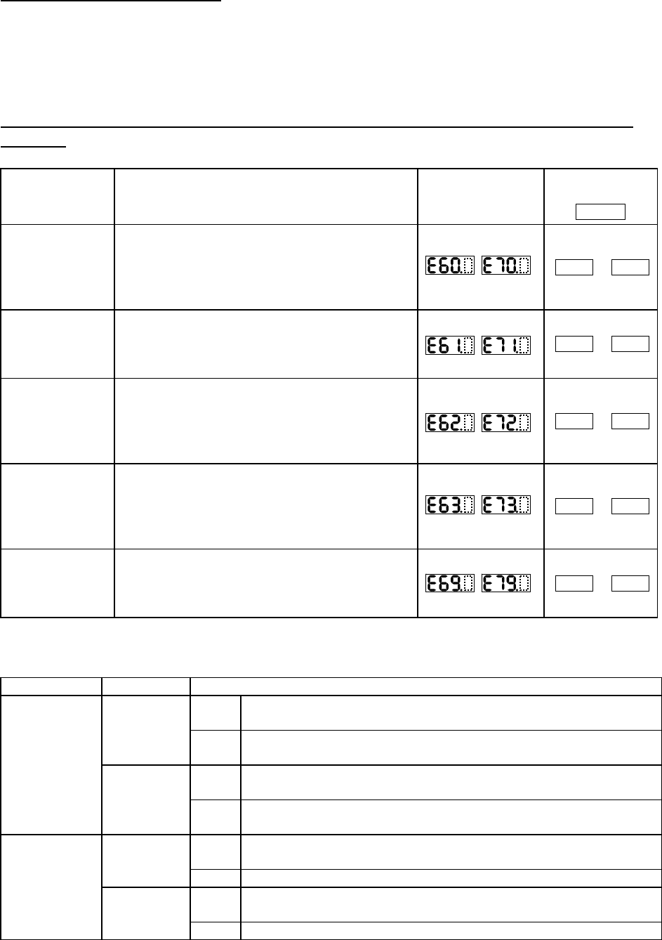
When an option board is mounted in the optional port 1 (located near the operator connector), the error
code display format is "E6*. " (on the digital operator) or "OP1-*" (on the remote operator). When it is
mounted in the optional port 2 (located near the control circuit terminal block), the error code display
format is "E7*. " (on the digital operator) or "OP2-*" (on the remote operator).
2.2.1 Error indications by protective functions with the feedback option board (SJ-FB)
mounted
Name Description
Display on digital
operator
Display on
remote operator
ERR1***
Encoder
disconnection
If the encoder wiring is disconnected, an encoder
connection error is detected, the encoder fails, or an
encoder that does not support line driver output is
used, the inverter will shut off its output and display
the error code shown on the right.
OP1-0
OP2-0
Excessive speed
If the motor speed rises to "maximum frequency
(A004) x over-speed error detection level (P026)" or
more, the inverter will shut off its output and display
the error code shown on the right.
OP1-1
OP2-1
Positioning error
If, in position control mode, the deviation of the
current position from that specified by the
positioning command increases to 1,000,000 pulses
or more, the inverter will shut off its output and
display the error code shown on the right.
OP1-2
OP2-2
Position control
range trip
In absolute position control mode, the inverter shuts
off its output and indicates an error when the range
specified by the position range specification
(forward) (P072) or position range specification
(reverse) (P073) is exceeded.
OP1-3
OP2-3
SJ-FB connection
error
If a faulty connection (i.e., mounting) of the
feedback option board is detected, the inverter will
shut off its output and display the error code shown
on the right.
OP1-9
OP2-9
Note: If the option board does not operate normally, confirm the DIP switch settings on the option board.
Functions of the DIP switches on the feedback option board (SJ-FB)
DIP switch Switch No. Setting
ON
Enabling the detection of encoder disconnection when the encoder
phases A and B are not connected
1
OFF
Disabling the detection of encoder disconnection when the encoder
phases A and B are not connected
ON
Enabling the detection of encoder disconnection when the encoder
phase Z is not connected
SWENC
2
OFF
Disabling the detection of encoder disconnection when the encoder
phase Z is not connected
ON
Enabling the terminating resistor between the SAP and SAN terminals
(150Ω)
1
OFF Disabling the terminating resistor between the SAP and SAN terminals
ON
Enabling the terminating resistor between the SBP and SBN terminals
(150Ω)
SWR
2
OFF Disabling the terminating resistor between the SBP and SBN terminals
Note: For details, refer to the instruction manual for the option board.


