


1 - 13
Default
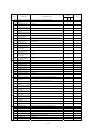
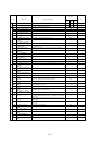
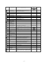
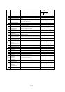
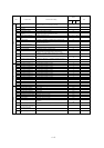
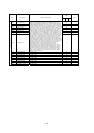
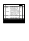
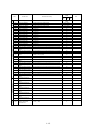
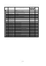
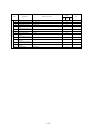
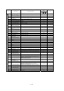
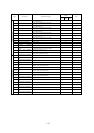
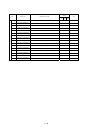
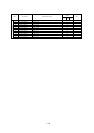
Code Function name Monitored data or setting
_FF _FEF _FUF
Note
Ter m
inal
C111 Overload setting (2) 0.0 to 2.00 x "rated current" (A)
Rated current of
inverter
C121 [O] input zero calibration 0. to 9999., 1000 to 6553 (10000 to 65530) Factory setting
C122 [OI] input zero calibration 0. to 9999., 1000 to 6553 (10000 to 65530) Factory setting
Adjust
ment
C123 [O2] input zero calibration 0. to 9999., 1000 to 6553 (10000 to 65530) Factory setting
C130 Output 11 on-delay time 0.0 to 100.0 (s) 0.0
C131 Output 11 off-delay time 0.0 to 100.0 (s) 0.0
C132 Output 12 on-delay time 0.0 to 100.0 (s) 0.0
C133 Output 12 off-delay time 0.0 to 100.0 (s) 0.0
C134 Output 13 on-delay time 0.0 to 100.0 (s) 0.0
C135 Output 13 off-delay time 0.0 to 100.0 (s) 0.0
C136 Output 14 on-delay time 0.0 to 100.0 (s) 0.0
C137 Output 14 off-delay time 0.0 to 100.0 (s) 0.0
C138 Output 15 on-delay time 0.0 to 100.0 (s) 0.0
C139 Output 15 off-delay time 0.0 to 100.0 (s) 0.0
C140 Output RY on-delay time 0.0 to 100.0 (s) 0.0
C141 Output RY off-delay time 0.0 to 100.0 (s) 0.0
C142 Logical output signal 1 selection 1 Same as the settings of C021 to C026 (except those of LOG1 to LOG6) 00
C143 Logical output signal 1 selection 2 Same as the settings of C021 to C026 (except those of LOG1 to LOG6) 00
C144
Logical output signal 1 operator
selection
00 (AND), 01 (OR), 02 (XOR) 00
C145 Logical output signal 2 selection 1 Same as the settings of C021 to C026 (except those of LOG1 to LOG6) 00
C146 Logical output signal 2 selection 2 Same as the settings of C021 to C026 (except those of LOG1 to LOG6) 00
C147
Logical output signal 2 operator
selection
00 (AND), 01 (OR), 02 (XOR) 00
C148 Logical output signal 3 selection 1 Same as the settings of C021 to C026 (except those of LOG1 to LOG6) 00
C149 Logical output signal 3 selection 2 Same as the settings of C021 to C026 (except those of LOG1 to LOG6) 00
C150
Logical output signal 3 operator
selection
00 (AND), 01 (OR), 02 (XOR) 00
C151 Logical output signal 4 selection 1 Same as the settings of C021 to C026 (except those of LOG1 to LOG6) 00
C152 Logical output signal 4 selection 2 Same as the settings of C021 to C026 (except those of LOG1 to LOG6) 00
C153
Logical output signal 4 operator
selection
00 (AND), 01 (OR), 02 (XOR) 00
C154 Logical output signal 5 selection 1 Same as the settings of C021 to C026 (except those of LOG1 to LOG6) 00
C155 Logical output signal 5 selection 2 Same as the settings of C021 to C026 (except those of LOG1 to LOG6) 00
C156
Logical output signal 5 operator
selection
00 (AND), 01 (OR), 02 (XOR) 00
C157 Logical output signal 6 selection 1 Same as the settings of C021 to C026 (except those of LOG1 to LOG6) 00
C158 Logical output signal 6 selection 2 Same as the settings of C021 to C026 (except those of LOG1 to LOG6) 00
Output terminal operation function
C159
Logical output signal 6 operator
selection
00 (AND), 01 (OR), 02 (XOR) 00
C160
Input terminal response time
setting 1
0. to 200. ( ¯2ms) 1
C161
Input terminal response time
setting 2
0. to 200. ( ¯2ms) 1
C162
Input terminal response time
setting 3
0. to 200. ( ¯2ms) 1
C163
Input terminal response time
setting 4
0. to 200. ( ¯2ms) 1
C164
Input terminal response time
setting 5
0. to 200. ( ¯2ms) 1
C165
Input terminal response time
setting 6
0. to 200. ( ¯2ms) 1
C166
Input terminal response time
setting 7
0. to 200. ( ¯2ms) 1
C167
Input terminal response time
setting 8
0. to 200. ( ¯2ms) 1
Input terminal response
C168
Input terminal response time
setting FW
0. to 200. ( ¯2ms) 1
Other
C169
Multistage speed/position
determination time
0. to 200. ( ¯10ms) 0