


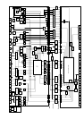
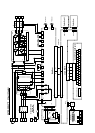
P N
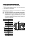
CB circuit
R S T
PKD PD
SCRG
N RB BRDG NN XG YG ZG UE VE WE UG VG WG P U W OH1 THF THP
THCOM
FF1 FF2
Inst. power
failure detect
Opt
coupler
Phase fail detect
Opt
coupler
Opt
coupler
Opt
coupler
RPHF RPHF RPHF IPL
(N)
Inrush current
limit circuit
Thyristor drive
circuit
(incl. suppress circuit)
Power supply
for THY gate
(5V)
Opt
coupler
SCR
BRD drive circuit
(suppress circuit)
Opt
coupler
BRD
(N) (L)
Lower arm drive circuit
(suppress circuit)
Power supply
for IGBT
lower arms
(PV15)
STR
(N)
Upper arm drive circuit
(suppress circuit)
GX GY GZ GS0 GU GV GW UN VN WN
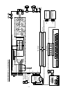
Power
supply for
IGBT upper
arm (U)
P
(N) (N) (N) (N) (N) (N) (N) (N) (N) (N) (N)
Current
detect (U)
Current
detect
(W)
Power supply for
control (+-12V)
IUF IWF PV12 L NV12
Temp.
error
detect
OH
(L) (L) (L) (L) (L)
(CM1)
(N)
Power supply
for control
(5V)
Power supply
for GA (5V)
Power supply
for I/F (24V)
PV5 L PV5N PV24 CM 1
Fan rotation
error detect
PV24
CM1
UV
UV detect
R0
T0
FAN
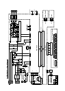
Opt
coupler
Inst. power
failure detect
Opt
coupler
IPL
GA
(5V)
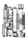
BRD
Voltage division
circuit
Phase
voltage
detection
OV detection
f - theta detection
Isolation AMP
Opt
coupler
Opt
coupler
VDC MVF1 MVF2IUF IWF THF THP THCOM PV12 L NV12
Opt
coupler
FFLT PV5 PV5NV12LPV12 PV5 LPV5 L L
(N)(N)(N) (L) (L) (N)
PV24 PV24 CM1 CM1 IPL
(CM1) (CM1) (N) (N) (L)
Opt
coupler
GS
High speed
opt coupler
WSVSUS
Opt
coupler
PHF
Opt
coupler
TRIPGASRSGASCKGARESTRESGARXD
Opt coupler
Opt
coupler
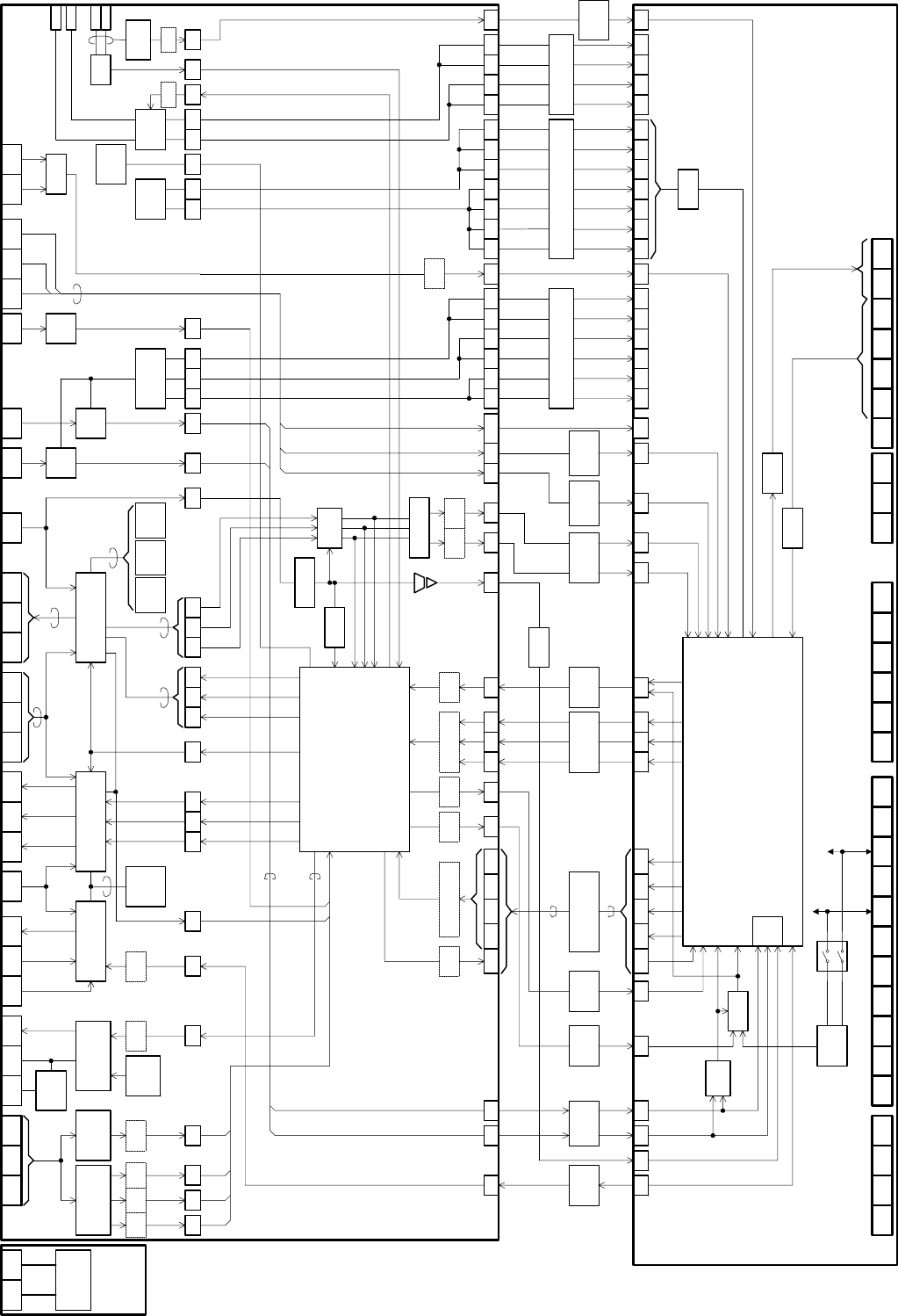
Main board
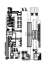
"H" when
BRD is ON
+-3.3Vpeak at
rated output
BRD IUF IWFVDC
"L" when
tripping
TRIP
SH Microprocessor (3.45V)
"L" when
phase loss
PHF
for communication.
Operates during
stopping.
GASRSGASCKGARESTRESGARXD WSVSUS
PWM signal
"L" when
gate
suppress
GS
apprx. 6.4V at
OV level
(U-V) (W-U)
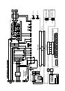
Temp.
detection on
heatsink
Temp.
detection on
PCB
THF THP PV5 PV5PV5 LPV5 L L
Power supply for digital signal
Signals for freq.
matching
MVF1 MVF2 PV12 L NV12 NV12LPV12
Power supply for analog signal
FFLT PV24 PV24 CM1 CM1
Power supply for I/F
"H" when
inst. power
failure
IPL
(L)(CM1)(CM1)(CM1)(CM1)(L)(L)(L)(L)(L)(L)(L)(L)(L)(L)(L)(L)(L)(L)(L)(L)(L)(L)(L)(L)(L)(L)(L)(L)(L)
(L)
(L) (L)
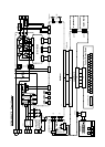
Control board
Output
shutoff circuit
Overcurrent
detection
Emergency
Stop
P24
A/D
CM1 CM1 PLC FW 8 7 6 5 4 3 2 1 TH FM CM2 15 14 13 12 11 AL0 AL1 AL2 H O O2 OI L AM AMI
AVR
A/D
12bit
D/A
10bit
Slide switch S1
40 signals between Main
board and control board
(L)
Power
supply for
IGBT upper
arm (V)
Power
supply for
IGBT upper
arm (W)
L