


5 - 6
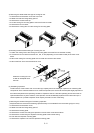
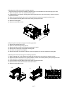
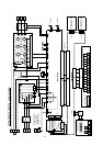
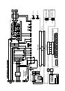
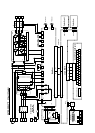
3) Removing the sheet-metal-case type of cooling-fan unit
<1> Remove the terminal block cover and front cover.
<2> Make sure that the Charge lamp goes off.
<3> Remove the screws at the top.
<4> Lift the cooling-fan mounting plate to remove it from the inverter.
<5> Remove the fan connector.
<6> Remove the cooling fans from the cooling-fan mounting plate.
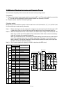
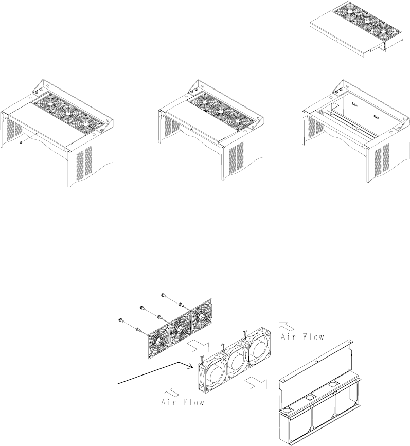
4) Mounting the sheet-metal-case type of cooling-fan unit
<1> Attach the cooling fans to the cooling-fan mounting plate so that the fans are oriented correctly.
<2> Connect the fan connector to terminal J21, J22, or J23 (depending on the inverter model) of the main circuit
board.
<3> Mount the cooling-fan mounting plate on the inverter and secure it with screws.
<4> Mount the front cover and terminal block cover.
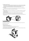
(2) Smoothing capacitors
The DC section of the inverter main circuit uses high-capacity aluminum electrolytic capacitors as smoothing filter
components. Since chemical reactions occur inside the capacitors, the service life of these parts largely depends on
the ambient temperature and operating conditions. Capacitors used in a standard operating environment must be
replaced after about 10 years. However, each capacitor must be immediately replaced if found abnormal upon a
visual inspection or if periodic inspection finds capacity to be 80% or less of the rating.
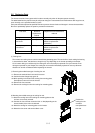
1) Removing the molded-case type of smoothing capacitors
(note)This feature to remove the smoothing capacitor easily is not available for the mold case type(up to 11Kw)
<1> Remove the terminal block cover.
<2> Make sure that the Charge lamp goes off.
<3> Remove the backing plate.
<4> Remove the screws connecting the capacitor unit to the main circuit terminal block.
<5> Remove the screws fixing the capacitor mounting plate to the inverter casing.
<6> Pull down the capacitor mounting plate.
<7> Remove the capacitor unit from the capacitor mounting plate.
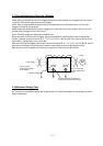
Position the cooling-fan unit
so that its nameplate faces
this side.