


3. Debug Mode
Specifying "01" (ON) for the debugging-mode selection function (C091) displays the functions described below.
Note: The debugging-mode selection function (C091) is not displayed when the factory settings are applied. To
enable the display of said function, specify "00" (ALL) for the display selection function (b037).
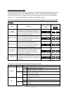
3.1 Monitor Modes
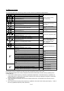
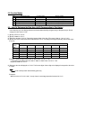
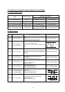
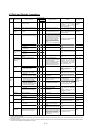
No.
Function name Function code Range of monitoring
1 Monitoring of control frequency d101 0.00-99.99/100.0-400.0(Hz)
2 Monitoring of trip factor determined
by gate array
d105 00-FF
3 Monitoring of MCU No d106 0000-9999
4 Monitoring of maximum voltage d109 0.0-999.9(V)
5 Monitoring of temperature on printed
circuit board
d110 -20.0-200.0(°C)
6 Monitoring of maximum temperature
on printed circuit board
d111 -20.0-200.0(°C)
Each monitoring function is described below.
(1)Monitoring of control frequency (d101)
This monitoring function displays on the monitor the final control frequency output by the inverter.
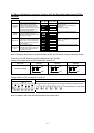
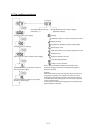
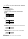
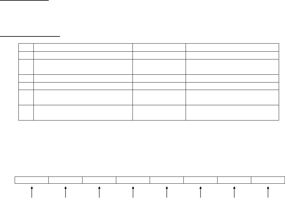
(2) Monitoring of trip factor determined by gate array (d105)
Upon detecting a trip factor, the gate array transfers an 8-bit signal indicating the trip factor to the MCU as follows:
bit7 bit6 bit5 bit4 bit3 bit2 bit1 bit0
Note 1: The phase of an IGBT error cannot be determined on inverter models in which a single power module is
mounted. In such cases, bit 6 indicates all IGBT errors.
Note 2: Error code "E20" is displayed upon the detection of lower cooling-fan speed.
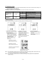
This monitoring function (d105) displays a hexadecimal code on the monitor.
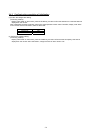
Example 1: Display of "10"
10 (hexadecimal) = 00010000 (binary)
Since bit 4 of the binary code is "1", this code indicates that a temperature error caused the trip.
Example 2: Display of "62"
62 (hexadecimal) = 01100010 (binary)
Since bits 6, 5, and 1 of the binary code are "1", this code indicates that IGBT errors in phases U, V, and W
caused the trip.
Note 3: This monitoring function can be used to check the trip content only while the inverter is in a tripping state.
See Section 3.3 for how to check the trip content according to the trip history.
Note 4: Normally, the inverter is automatically self-reset periodically from the trip due to undervoltage detected by
the gate array. Therefore, bit 2 of the trip factor signal may not be set to "1" even if undervoltage occurs.
Also note that undervoltage may be detected as a gate array error (E25) in case of undervoltage signal chatter.
(3)Monitoring of MCU No. (d106)
This monitoring function displays the software management number of preinstalled MCU software.
(4) Monitoring of maximum voltage (d109)
This monitoring function displays the maximum voltage detected across terminals P and N while the inverter is
stopped.
(5) Monitoring of temperature on printed circuit board (d110)
This monitoring function displays the temperature on the printed board of main circuit in the power module.
(6) Monitoring of maximum temperature on printed circuit board (d111)
This monitoring function displays the maximun temperature on the printed board of main circuite board in the
power module.
Gate array
error
(E25)
IGBT error
Phase W
(E30)
*NOTE1
IGBT error
Phase V
(E30)
*NOTE1
Temperature
error
(E20 or E21)
*NOTE2
Undervoltage
(E09)
*NOTE3
IGBT error
Phase U
(E30)
*NOTE1
Overvoltage
protection
(E07)
Ground
fault of
optional unit
(E14