


5 - 8
(3) Smoothing capacitors (on PCB)
Smoothing capacitors on PCB is recommended to be replaced after 10 years of usage under standard installation,
which is the same as main Smoothing capacitors. If abnormality is found by visual inspection and/or if the control
power supply is not activated after the power ON, the capacitors are required to be replaced.
(The replacement is done by the PCB replacement, since the capacitors themselves cannot be replaced.)
(How to replace)
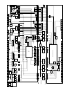
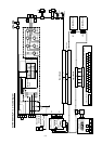
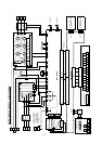
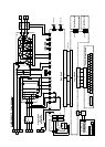
The replacement is done by refering to the structure diagram attached. Please pay attention to the length of the
screws. Make sure you're using the correct screws when re-assembling.
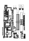
(Note)
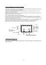
Please pay attention to the tab portion when disassembling. There is a possibility of damaging the mold case type.
(model up to 22kW.)
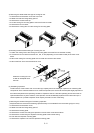
<1> Remove the terminal block cover, front cover and cooling fan mounting plate, which is the same procedure as
cooling fan replacement.
<2>Remove the connection cable (flat cable), which is connected to the control board and main board.
<3>Remove the cable fixing plate and short circuit bar attached to the P-PD terminal of the main board.
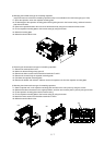
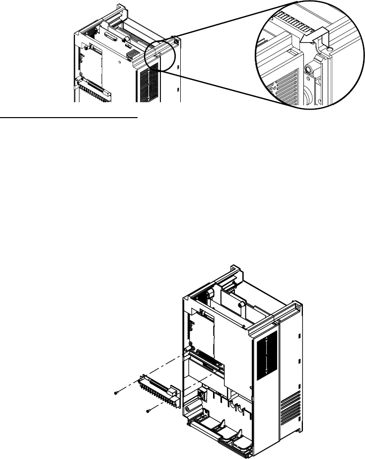
<4>Remove two screws on the mold case, and remove the case as shown in figure below. Please pay attention not to
damage the tabs.
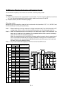
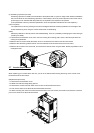
5.7 Inverter Replacement
When replacing your inverter with a new one, you can do so without disconnecting the wiring on the control circuit
terminal block of the old inverter.
(Replacement procedure)
<1> Remove the terminal block cover.
<2> Make sure that the Charge lamp goes off.
<3> Remove the screws from both sides of the control circuit terminal block board.
<4> Pull out the control circuit terminal block board toward the front.
<5> When mounting the control circuit terminal block board on the new inverter, be careful not to bend the connector
pins on the control circuit terminal block board.