


15
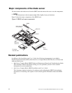
System board illustration
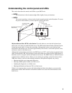
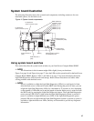
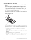
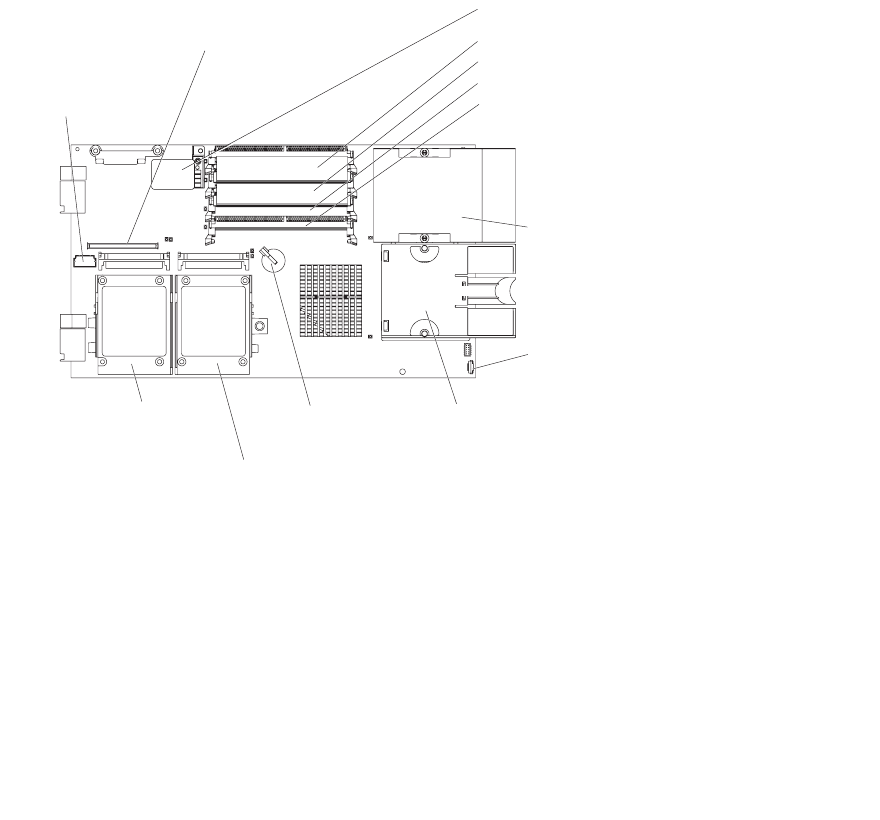
The following illustration shows the system-board components, including connectors for user-
installable options, for the blade server.
Figure 4. System board components.
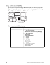
Using system board switches
This section describes the system board switches on your Intel Server Compute Blade SBX82.
✏ NOTE
The illustrations in this document might differ slightly from your hardware.
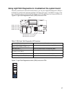
Figure 5 on page 16 and Figure 6 on page 17 show the LEDs on the system board for the Intel Server
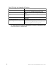
Compute Blade SBX82. Refer to Table 1 and Table 2 on page 17 for more information about the
Light Path Diagnostics LED locations and settings. Refer to these illustrations and tables when
solving problems with the blade server.
✏ NOTE
Power is available to relight the Light Path Diagnostics LEDs for a small period of time
after the blade server is removed from the SBCE unit. During that period of time, you can
relight the Light Path Diagnostics LEDs for a maximum of 25 seconds (or less, depending
on the number of LEDs that are lit and the length of time the blade server is removed from
the SBCE unit) by pressing the Light Path Diagnostics button. The Light Path Diagnostics
power present LED (CR111) lights when the Light Path Diagnostics button is pressed if
power is available to relight the blade-error LEDs. If the Light Path Diagnostics power
present LED does not light when the Light Path Diagnostics button is pressed, no power is
available to light the blade-error LEDs, and they will be unable to provide any diagnostic
information.
BatterySCSI connector 2
(J94)
SCSI connector 1
(J95)
DIMM 1 (J113)
DIMM 2 (J111)
DIMM 3 (J112)
DIMM 4 (J110)
Microprocessor 1
and heatsink (U66)
Microprocessor socket 2
and heatsink (U70)
Control panel
connector (J64)
Blade expansion
connector (J132)
I/O expansion
option connector (J131)
I/O expansion
option connector (J34)