


B-3
SP-100
Return to Section TOC Return to Section TOC Return to Section TOC Return to Section TOC
Return to Master TOC Return to Master TOC Return to Master TOC Return to Master TOC
OPERATION
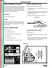
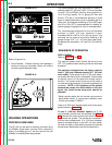
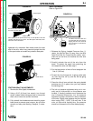
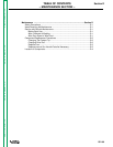
FIGURE B.1a
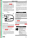
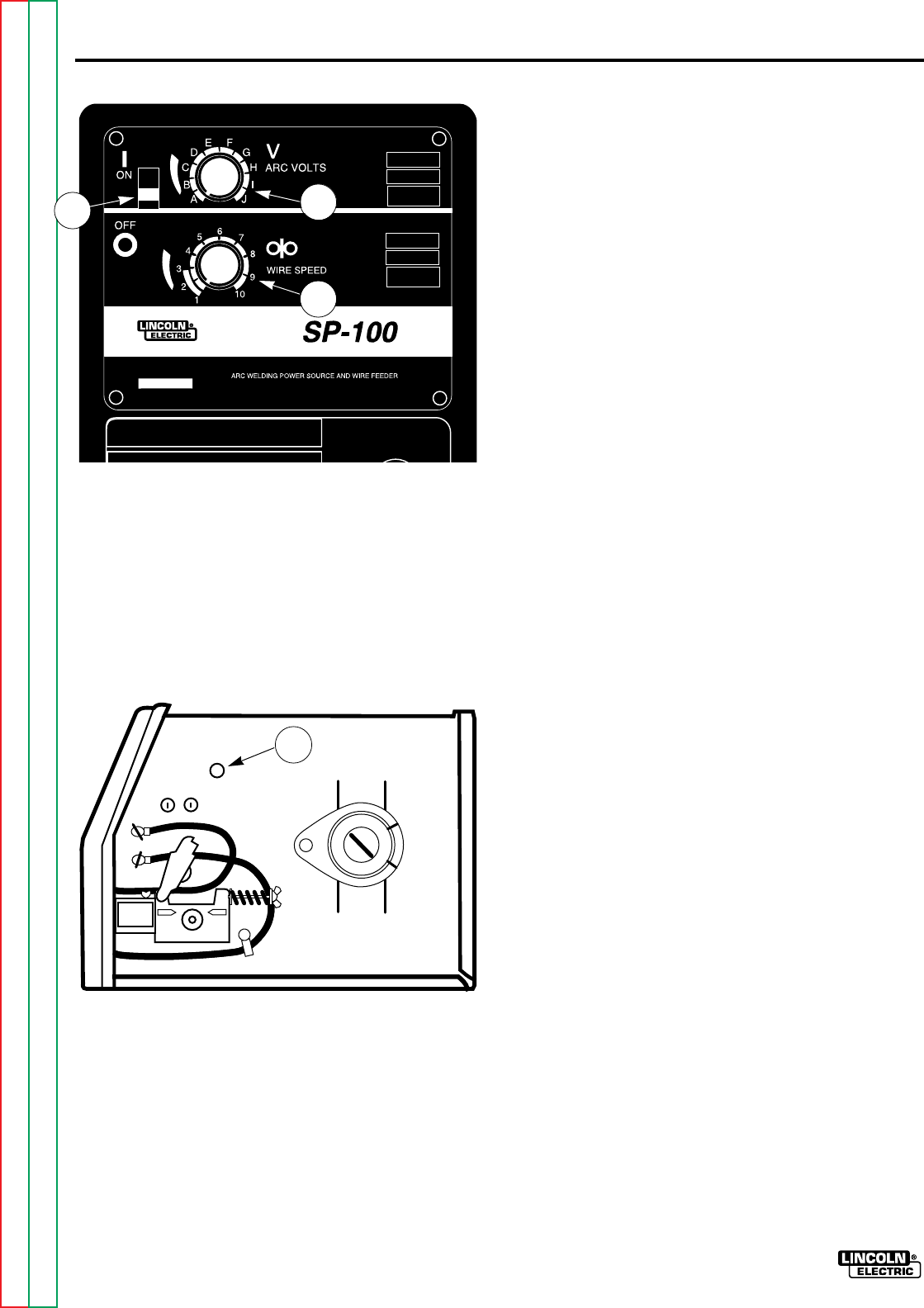
Refer to Figure B-1b.
4. Circuit Breaker - Protects machine from damage if
maximum output is exceeded. Button will extend
out when tripped (Manual reset).
FIGURE B.1b
WELDING OPERATIONS
PROCESS GUIDELINES
The SP-100 can be used for welding mild steel using
the GMAW, single pass, process which requires a
supply of shielding gas or it can be used for the self
shielded, Innershield electrode process.
The recommended gas and electrode for GMAW is
welding grade CO
2
gas and 0.025” (0 6 mm) diameter
Lincoln L-56 mild-steel welding wire [supplied on
121/2 Ib (6 kg) spools]. For 14 gauge (2,0 mm) and
thinner, CO
2
gas is recommended because it gives
equal or better performance than a blended gas at a
lower cost. A mixed gas consisting of 75 to 80% Argon
and 20 to 25% CO
2
is recommended for welding on
heavier gauge [12 gauge (2,5 mm) for example] steel.
The recommended electrode for the self-shielded
process is 0.035” (0,9 mm) diameter Lincoln
Innershield NR-211-MP on 10 Ib (4,5 kg) spools. This
electrode can be used for all position welding of 20
gauge through 5/16” (1 0 – 8,0 mm) thick steel [multi-
ple passes are required for 1/4” and 5/16” (6,0 and 8,0
mm)].
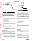
SEQUENCE OF OPERATION
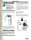
WIRE LOADING
Refer to Figure B.2. and B.3.
The machine power switch should be turned to the
OFF (“O”) position before working inside the wire feed
enclosure.
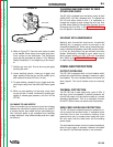
The machine is shipped from the factory ready to
feed 8” (200 mm) diameter spools [2.2” (56 mm)
max. width]. These spools fit on a 2” (50 mm) diame-
ter spindle that has a built-in adjustable* friction brake
to prevent overrun of the spool and excess slack in
the wire. The thumb screw at the end of the shaft is
not intended to be loosened. It should be tightened full
clockwise. NOTE: If full tightening of the spindle
thumbscrew causes too much tension in the wire
spool, the thumb screw stop point should be
adjusted.
*Earlier spindle shafts did not include a set screw to
adjust brake friction. If a set screw is desired, order
Lincoln part number T12932-2.
Load an 8” (200 mm) diameter spool on the wire spool
spindle shown in Figure B.2.
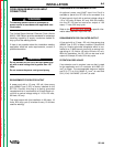
To use 4” (100 mm) diameter spools, the 2” (50
mm) diameter spindle must be removed (See Figure
B.3). Remove the thumb screw at the end of the shaft
and remove the spindle. The spindle can be stored in
the wire feed compartment. A 4’ (100 mm) diameter
spool is mounted directly on the 5/8” (16 mm) diame-
ter shaft and held in place with the previously removed
thumb screw. Make certain that the thumbscrew is
3
2
1
4