


B-5
SP-100
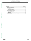
Return to Section TOC Return to Section TOC Return to Section TOC Return to Section TOC
Return to Master TOC Return to Master TOC Return to Master TOC Return to Master TOC
OPERATION
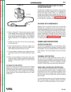
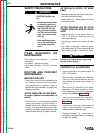
When inching the welding wire, the drive rolls, the
gun connector block and the gun contact tip are
always energized relative to work and ground and
remain energized several seconds after the gun
trigger is released.
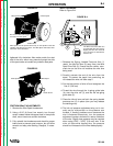
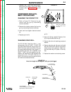
7. Refer to Figure B.5. Remove gas nozzle and con-
tact tip from end of gun.
8. Turn the SP-100 ON (“I”).
9. Straighten the gun cable assembly.
10. Depress the gun trigger switch and feed welding
wire through the gun and cable. (Point gun away
from yourself and others while feeding wire.)
Release gun trigger after wire appears at end of
gun.
11. Replace contact tip and gas nozzle.
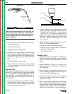
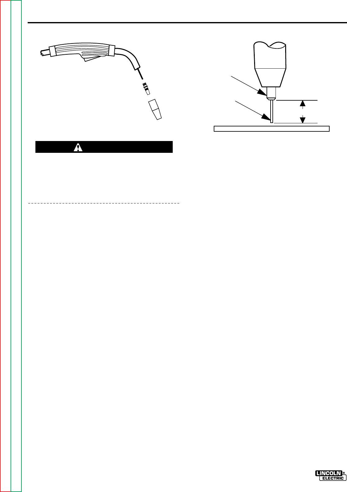
12. Refer to Figure B-6. Cut the wire off 1/4” – 3/8” (6
– 10 mm) from the end of the tip. The SP-100 is
now ready to weld.
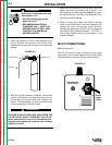
SHIELDING GAS
When using the GMAW process, a cylinder of carbon
dioxide (CO
2
) or argon-carbon dioxide mixed shielding
gas, flow regulator, and an inlet gas hose must be
obtained. Refer to the ACCESSORIES section for
more information about selecting gas cylinders for use
with the SP-100.
1. For CO
2
, open the cylinder very slowly. For argon-
mixed gas, open cylinder valve slowly a fraction of
a turn. When the cylinder pressure gauge pointer
stops moving, open the valve fully.
FIGURE B.6FIGURE B.5
Gun Handle
Gas Diffuser/
Contact Tip
Gas Nozzle
WARNING
2. If using a regulator with an adjustable flow meter,
close the gun trigger and adjust the flow to give 15
– 20 cubic ft per hour (CFH) (7 – 10 I/min) [use 20
-– 25 CFH (10 – 12 I/min) when welding out of
position or in a drafty location for CO
2
]. For argon
mixed gas, trigger to release gas pressure, and
turn off the adjust the flow to give 25 – 30 CFH
(12 – 14 I/min).
3. Keep the cylinder valve closed, except when using
the SP-100. When finished welding:
a) Close the cylinder valve to stop gas flow.
b) Depress the gun trigger briefly to release the
pressure in the gas hose.
c) Turn off the SP-100.
MAKING A WELD
1. See Recommended Processes And Equipment
section for selection of welding wire and shielding
gas and for range of metal thicknesses that can be
welded.
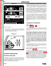
2. See the Application Guide on the inside of wire
feed section door for information on setting the
SP-100 controls.
3. Set the Voltage (“V”) and Wire Speed (“olo’”) con-
trols to the settings suggested for the welding wire
and base metal thickness being used.
4. Check that the polarity is correct for the welding
wire being used and that the gas supply, if
required, is turned on.
5. When using Innershield electrode, remove the gas
nozzle and install the gasless nozzle. This will
improve visibility of the arc and protect the gas dif-
fuser from weld spatter. Refer to the MAINTE-
NANCE section for details on nozzle replacement.
3/8" – 1/2" Electrical Stickout
Contact Tip
Wire Electrode