


SP-100
Return to Section TOC Return to Section TOC Return to Section TOC Return to Section TOC
Return to Master TOC Return to Master TOC Return to Master TOC Return to Master TOC
E-1
THEORY OF OPERATION
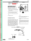
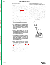
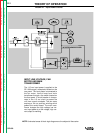
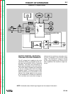
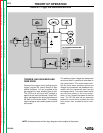
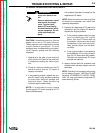
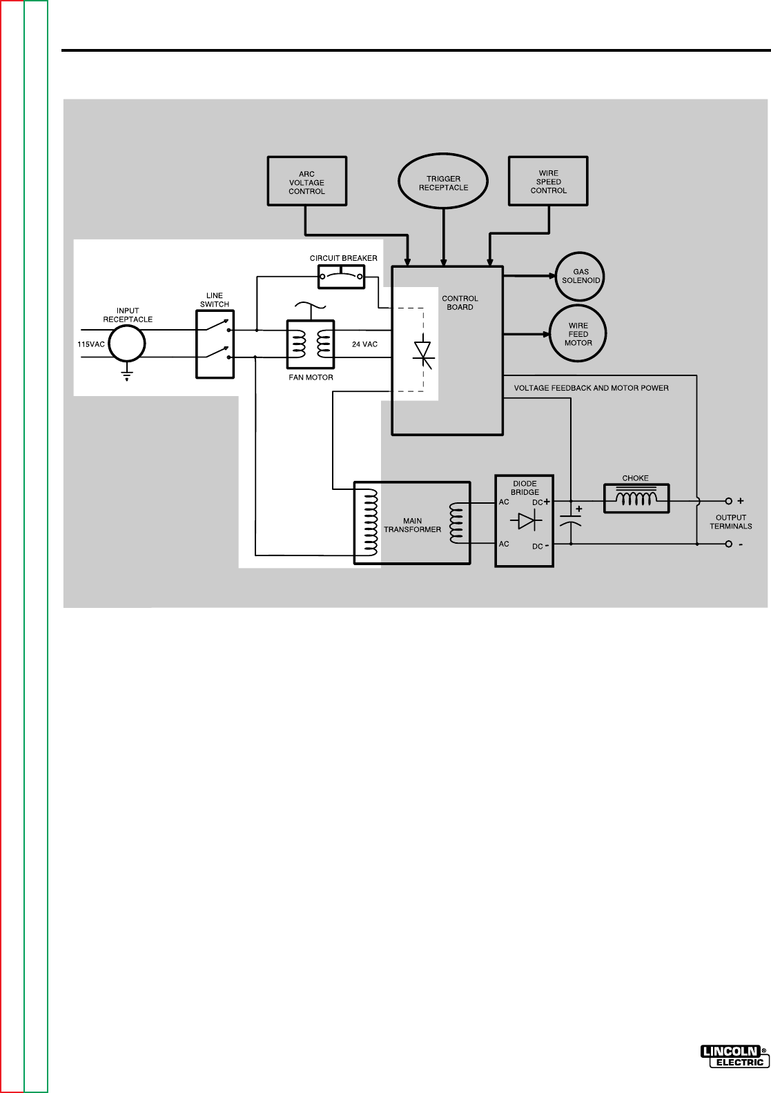
NOTE: Unshaded areas of block logic diagram are the subject of discussion.
INPUT LINE VOLTAGE, FAN
MOTOR AND MAIN
TRANSFORMER
The 115 vac input power is applied to the
SP-100 through a receptacle located on the
rear panel. The input power is connected to
the fan motor, control board and main
transformer through a line switch located on
the front panel. A circuit breaker is incorpo-
rated in the 115 vac circuit to protect the
unit from current overloads. The fan motor
employs a 24 vac auxiliary winding which
powers the control board. The main trans-
former changes the high voltage, low cur-
rent input power to a low voltage, high cur-
rent output for welding.
FIGURE E.1 – Input Power Circuits