


SP-100
Return to Section TOC Return to Section TOC Return to Section TOC Return to Section TOC
Return to Master TOC Return to Master TOC Return to Master TOC Return to Master TOC
F-11
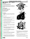
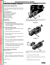
TROUBLESHOOTING & REPAIR
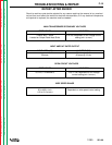
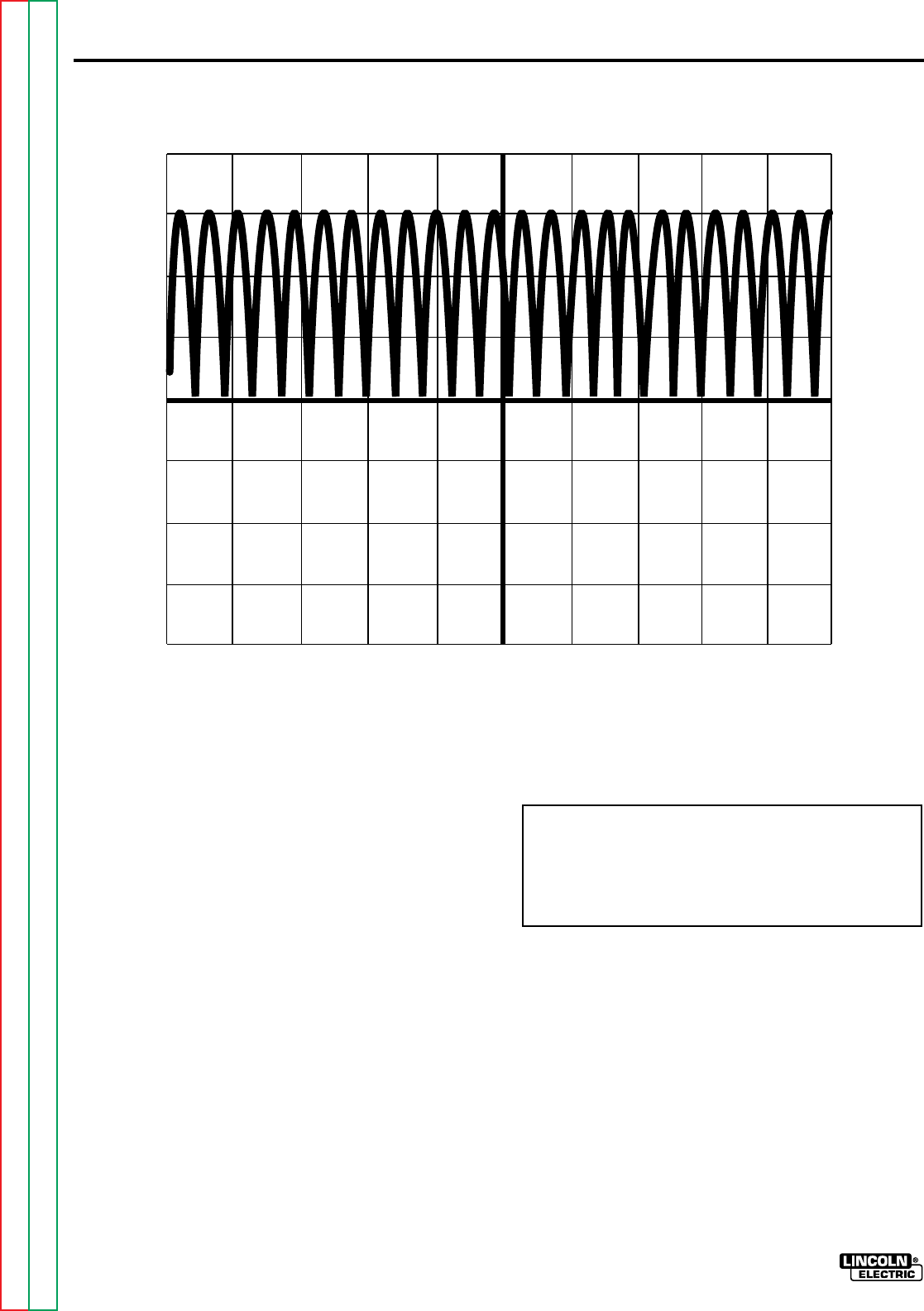
SCOPE SETTINGS
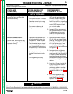
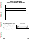
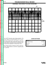
This is NOT the typical output voltage waveform. The
output capacitor was disconnected from the circuit.
Note the increased ripple in the waveform. This condi-
tion simulates the faulty output filter capacitor. Each
vertical division represents 10 volts and that each hor-
izontal division represents 20 milliseconds in time.
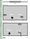
Note: Scope probes connected at machine output ter-
minals. Positive probe to (+) terminal, negative probe
to (–) terminal.
ABNORMAL OPEN CIRCUIT VOLTAGE WAVEFORM
0
volts
10 volts 20 ms
C1
Volts/Div ........................................................10/Div
Horizontal Sweep.....................................20 ms/Div
Coupling .............................................................DC
Trigger..........................................................Internal