


SP-100
Return to Section TOC Return to Section TOC Return to Section TOC Return to Section TOC
Return to Master TOC Return to Master TOC Return to Master TOC Return to Master TOC
E-2
THEORY OF OPERATION
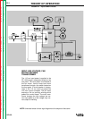
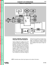
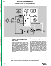
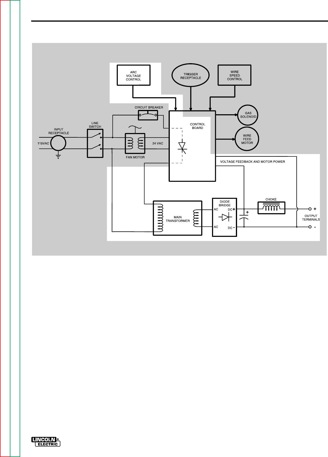
NOTE: Unshaded areas of block logic diagram are the subject of discussion.
OUTPUT CONTROL, RECTIFICA-
TION AND VOLTAGE FEEDBACK
The AC voltage that is applied to the main
transformer primary is controlled at the con-
trol board by two SCR’s (Silicon Controlled
Rectifiers). The SCR’s are controlled by a
pulse signal developed on the control board.
The control board compares the commands
of the arc voltage control with the voltage
feedback signal. The board circuitry then
sends a pulse to turn on the SCR’s. In this
manner, the voltage applied to the primary
of the transformer is varied and controlled.
This variable and controlled voltage is
FIGURE E.2 – Output Circuits
reflected at the transformer secondary wind-
ing and is applied to the rectifier diode
bridge. This rectified DC voltage is filtered
by the output capacitor and choke circuit
and is applied to the machine’s output ter-
minals.