


SP-100
Return to Section TOC Return to Section TOC Return to Section TOC Return to Section TOC
Return to Master TOC Return to Master TOC Return to Master TOC Return to Master TOC
E-4
THEORY OF OPERATION
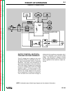
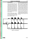
An SCR is fired by a short burst of current
into the gate. This gate pules must be more
positive than the cathode voltage. Since
there is a standard PN junction between
gate and cathode, the voltage between
these terminals must be slightly greater
than 0.6V. Once the SCR has fired, it is not
necessary to continue the flow of gate cur-
rent. As long as current continues to flow
from anode to cathode, the SCR will remain
on. When the anode to cathode current
drops below a minimum value, called hold-
ing current, the SCR will shut off. This nor-
mally occurs as the AC voltage passes
through zero into the negative portion of the
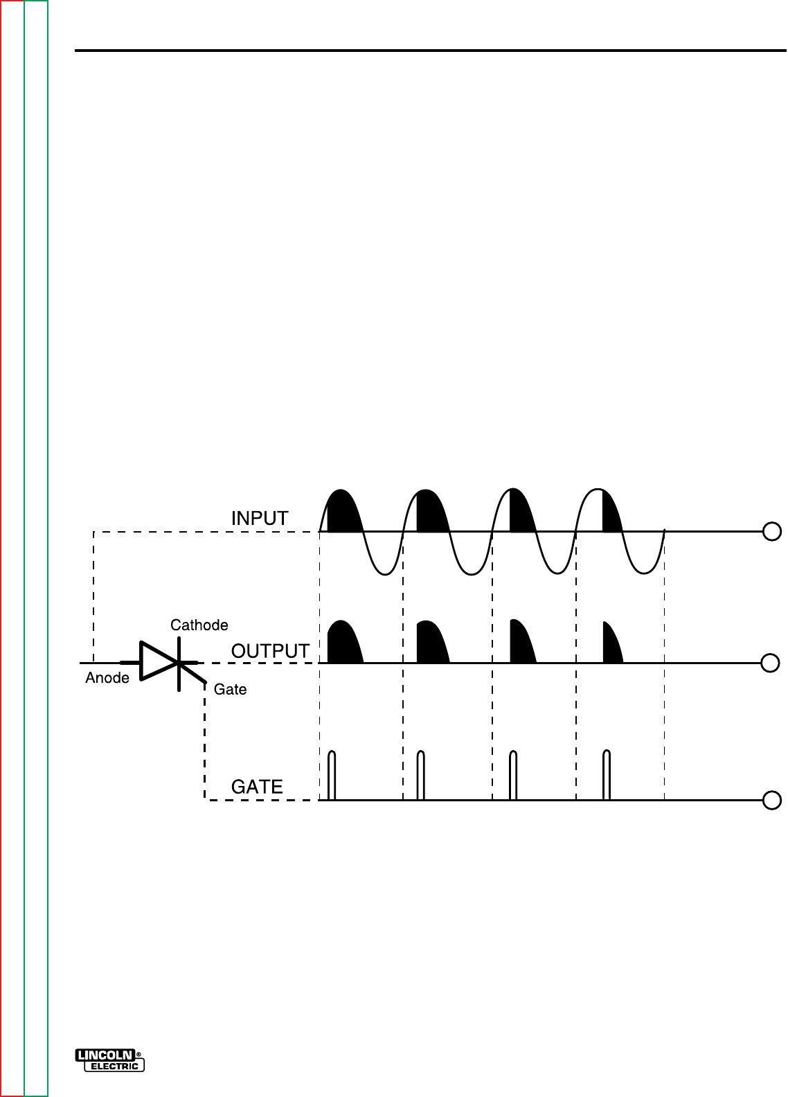
sine wave. If the SCR is turned on early in
the positive half cycle, the conduction time
is longer, resulting in greater SCR output. If
the gate firing occurs later in the cycle, the
conduction time is less, resulting in lower
SCR output.
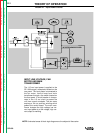
SCR OPERATION
A silicon controlled rectifier (SCR) is a three
terminal device used to control large cur-
rents to a load. An SCR acts very much like
a switch. When it is turned on there is cur-
rent flow from anode to cathode. In the ON
state, the SCR acts like a closed switch.
When the SCR is turned OFF, there is no
current flow from anode to cathode, thus the
device acts like an open switch. As the
name suggests, the SCR is a rectifier, so it
passes current only during positive half
cycles of the AC supply. The positive half
cycle is the portion of the sine wave in
which the anode of the SCR is more posi-
tive than the cathode.
When an AC supply voltage is applied to
the SCR, the device spends a certain por-
tion of the AC cycle time in the ON state
and the remainder of the time in the OFF
state. The amount of time spent in each
state is controlled by the Gate.
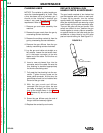
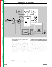
Note: As the gate pulse is applied later in the cycle, the SCR output is decreased.
FIGURE E.4 SCR OPERATION