


B-4
SP-100
Return to Section TOC Return to Section TOC Return to Section TOC Return to Section TOC
Return to Master TOC Return to Master TOC Return to Master TOC Return to Master TOC
OPERATION
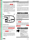
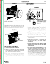
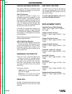
tightened fully clockwise. Also make certain the start
end of the wire, which may protrude through the side
of the spool does not contact any metallic case parts.
FIGURE B.3
FRICTION BRAKE ADJUSTMENTS
1. Remove the Wire Spool thumbscrew.
2. Using a 3/16” (4,8 mm) hex wrench, turn the set
screw, located inside the tapped hole in the spindle
shaft, one or two turns counter-clockwise.
3. Fully reinstall the thumbscrew and check for proper
brake force to prevent spool overrun, but still allow
smooth and easy wire feeding. Readjust, if neces-
sary.
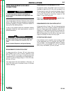
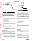
WIRE THREADING
Refer to Figure B-4
1. Release the Spring Loaded Pressure Arm (1)
rotate the Idle Roll Arm (2) away from. the Wire
Feed Drive Roll (3). Ensure that the visible, .sten-
ciled size on the drive roll matches the wire size
being used.
2. Carefully detach the end of the wire from the
spool. To prevent the spool from unwinding, do
not release the wire until after step 5.
3. Cut the bent portion of wire off and straighten the
first 4” (100 mm).
4. Thread the wire through the In-going guide tube
(4), over the drive roll (3), and into the out-going
guide tube (5).
5. Close the idle roll arm and latch the spring loaded
pressure arm (2) in place (now you may release
the welding wire).
6. The idle roll pressure adjustment wing nut is nor-
mally set for mid-position on the pressure arm
threads. If feeding problems occur because the
wire is flattened excessively, turn the pressure
adjustment counter-clockwise to reduce distortion
of the wire. Slightly less pressure may be required
when using 0.023 – 0.025” (0,6 mm) wire. If the
drive roll slips while feeding wire, the pressure
should be increased until the wire feeds properly.
FIGURE B.4
The Wire Drive Feed Roll can
accommodate two wire sizes by
flipping the wire drive feed roll
over. The sizes are stenciled on
the drive roll.
1
2
3
4
5
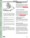
Wire Spindle Shaft
4" Wire Spool
Thumb Screw
To Wire Drive
Wire Spool must be pushed all the way on the spindle so that the
spindle’s tab will hold it in place. The Wire Spool will rotate clock-
wise when wire is dereeled.
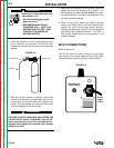
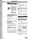
8” Wire Spool
Wire Spool Spindle
Be sure that this stud engages
the hole in the wire spool.
To Wire Drive
FIGURE B.2