


SP-100
Return to Section TOC Return to Section TOC Return to Section TOC Return to Section TOC
Return to Master TOC Return to Master TOC Return to Master TOC Return to Master TOC
D-2
MAINTENANCE
1. Make certain the SP-100 power switch is
off “O”.
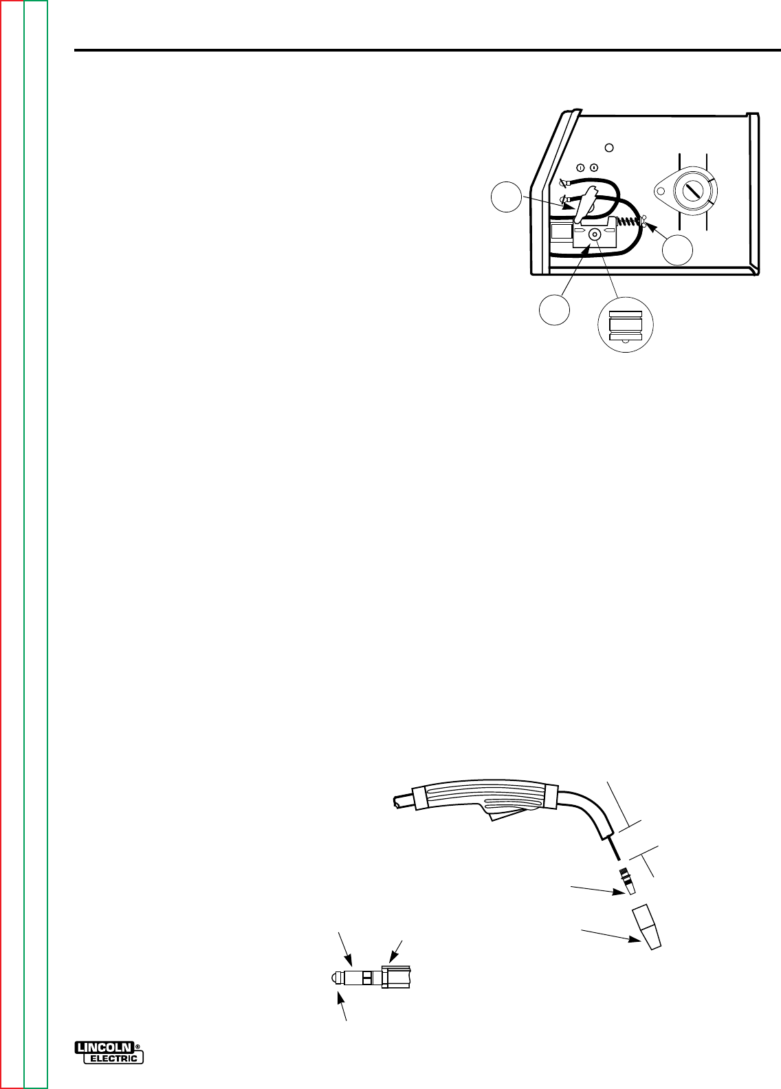
2. Open the Spring Loaded Pressure Arm
(2); Lift up the Idle Roll Arm (3).
3. Remove the drive roll retaining screw and
washer.
4. Remove the drive roll, flip over and install
with the 0.030/0.035” (0.8/0.9 mm) stencil
visible (away from gearbox). Make cer-
tain the small key is in place in the key-
way.
5. Replace the washer and retaining screw.
• Replace Liner – when wire feeding prob-
lems occur and other items have been
checked (refer to Changing Liner, in this
section).
COMPONENT REPLACE-
MENT PROCEDURES
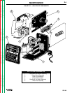
CHANGING THE CONTACT TIP
1. Refer to Figure D.2. Remove the gas
nozzle from the gun by unscrewing
counter-clockwise.
2. Remove the existing contact tip from the
gun by unscrewing counter-clockwise.
3. Insert and hand tighten desired contact
tip.
4. Replace gas nozzle.
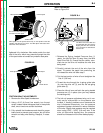
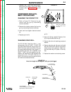
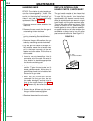
CHANGING DRIVE ROLL
The SP-100 Wire Feed Drive Roll (1 ) has
two grooves; one for 0.023” – 0.025” (0,6
mm) solid steel electrode and the other for
0.030” (0,8 mm) solid and 0.035” (O,9 mm)
flux-cored steel electrode. See Figure D.1.
As shipped, the drive roll is installed in the
0.023” – 0.025” (0,6 mm) position (as indi-
cated by the stenciling on the exposed side
of the drive roll). If 0.030” (0,8 mm) or
0.035” (0,9 mm) wire is to be used, the drive
roll must be reversed as follows:
Wire size is stenciled
on the ends of the
drive roll.
3
2
1
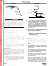
1-1/4 (31.8 mm)
Liner Trim Length
Gas Diffuser
Gas Nozzle or
Gasless Nozzle
Set Screw Brass Cable
Connector
Liner Assembly
(Liner bushing to be sealed tight
against brass cable connector)
FIGURE D.2
Liner trim length for the Magnum 100L gun (red trigger)
FIGURE D.1