


Return to Section TOC Return to Section TOC Return to Section TOC Return to Section TOC
Return to Master TOC Return to Master TOC Return to Master TOC Return to Master TOC
A-16
INSTALLATION
LN-8
A-16
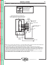
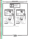
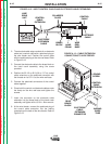
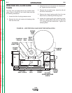
2. The standard cable setup consists of an electrode
cable and a control cable with a polarized plug on
the wire feeder end. Position the control cable
with the polarized plug at the wire reel base. Refer
to Figure A.12.
3. Connect the electrode cable to the brass block on
the hand crank assembly using the screw
provided.
4. Position the 22-1/2 or 45 ft (6.9 or 13.7 m) control
cable extension so the polarized connector with
the threads on its O.D. is at the wire reel base.
5. Connect the polarized connectors of the control
cable together.
6. Place both the control and electrode cables under
the clamp on the wire reel base and tighten the
screws.
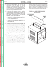
7. Insert the connector on the electrode cable
extension into the brass block of the hand crank
assembly and tighten with a 3/16 in. Allen wrench.
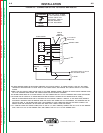
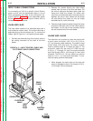
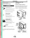
8. At the wire feeder, connect the polarized plug of
the control cable extension into the mating
receptacle on the back of the wire feeder. Refer to
Figure A.13.
FIGURE A.13 – CABLE EXTENSION
CONNECTIONS TO WIRE FEEDER
WIRE
DRIVE
UNIT
CONTROL
CABLE
EXTENSION
POLARIZED
PLUGS
CONTROL
CABLE
ELECTRODE
CABLE
HAND
CRANK
BRASS
BLOCK
ELECTRODE
EXTENSION
CABLE
WIRE
REEL
BASE
FIGURE A.12 – INPUT CONTROL CABLE AND ELECTRODE CABLE EXTENSIONS
LOCKING
SCREW
CONTROL
CABLE
EXTENSION
REAR
BRASS
BLOCK
ELECTRODE
CABLE
EXTENSION
CONNECTOR
INGOING
GUIDE
TUBE