


F-23
TROUBLESHOOTING AND REPAIR
F-23
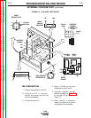
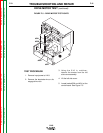
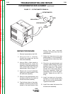
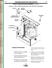
To further check the drive motor:
12. Remove input power (115VAC)
from the LN-8.
13. Locate and remove leads #539
and #541 from the control board,
see Figure F.5.
14. Locate and remove leads #626
and #627 from the relay board.
15. Using the ohmmeter, measure the
resistances per Table F.3.
16. If the motor resistance test is
good, proceed to the Motor
Applied Voltage Test.
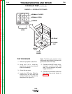
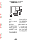
MOTOR APPLIED
VOLTAGE TEST
1. Carefully connect the isolated
120VDC supply (supply turned off)
to motor leads #626 and #627, see
Figure F.5.
2. Carefully connect the variable 0 to
120VDC supply (supply turned off)
to motor leads #539 and #541.
3. Apply field voltage first (leads #626
and #627) to the motor. Then
slowly apply the armature voltage
at leads #539 and #541.
4. The motor should run and the
speed should vary with changes to
the armature voltage.
5. If the motor does NOT run and
change speed correctly, the motor
or gear box may be faulty.
6. To stop the motor, remove the
armature voltage first, leads #539
and #541.
AFTER TESTING
1. Replace motor leads.
2. Install the screws that secure the
left side cover assembly.
3. If disengaged, engage the drive
rolls.
4. If removed, feed the electrode
back into the wire drive unit.
DRIVE MOTOR TEST (continued)
LN-8
Return to Section TOC Return to Section TOC Return to Section TOC Return to Section TOC
Return to Master TOC Return to Master TOC Return to Master TOC Return to Master TOC
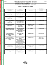
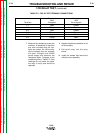
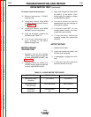
TEST POINTS RESISTANCE DC VOLTAGE
Lead #539 to #541 3 to 5 ohms 0 to 90VDC
Armature
Lead #626 to #627 750 to 950 ohms 90 to 120VDC
Field Winding
All leads to 500,000 ohms N/A
motor shell min.
TABLE F.3 – DRIVE MOTOR TEST POINTS