


F-22
TROUBLESHOOTING AND REPAIR
F-22
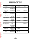
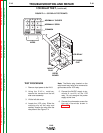
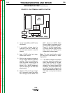
6. Locate leads #626 and #627 at the
relay board.
7. If a variable voltage board is
installed in the LN-8, make cer-
tain the mode switch is in the CV
position.
8. Apply 115VAC to the input recep-
tacle at pins C and D.
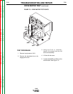
9. With the gun trigger activated or
the gun trigger terminals jumpered
together, (see wiring diagram),
check the motor armature volts at
leads #541 (+) and #539 (-).
Normal is 5 to 95VDC dependent
upon the setting of the wire feed
speed control.
10. With the LN-8 at idle (gun trigger
NOT activated) check the motor
field voltage at lead #626 and
#627. Normal is 115VDC. When
the gun trigger is activated or the
gun terminals jumpered together,
Figure F.6, the field voltage polari-
ty should reverse from the idle
state. Normal is 115VDC and is
independent of motor speed.
Note: The wire feed direction switch
(S3) must be in the forward, or “weld-
ing” position.
11. If the above voltages are present
and motor does not operate, the
motor, motor brushes, or the gear
box may be faulty. If the armature
voltage is not correct (leads #539
and #541), the control board may
be faulty. If the field voltage is not
correct (leads #626 and #627), the
1CR relay or relay board may be
faulty.
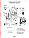
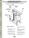
DRIVE MOTOR TEST (continued)
FIGURE F.6 – GUN TERMINAL JUMPER LOCATIONS
LN-8
Return to Section TOC Return to Section TOC Return to Section TOC Return to Section TOC
Return to Master TOC Return to Master TOC Return to Master TOC Return to Master TOC
1CR
RELAY
627
626
7 529 32A 524(A) 525(A)
LN-8 RELAY