


Return to Section TOC Return to Section TOC Return to Section TOC Return to Section TOC
Return to Master TOC Return to Master TOC Return to Master TOC Return to Master TOC
F-19
TROUBLESHOOTING AND REPAIR
F-19
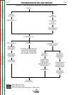
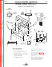
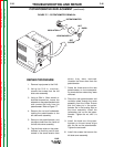
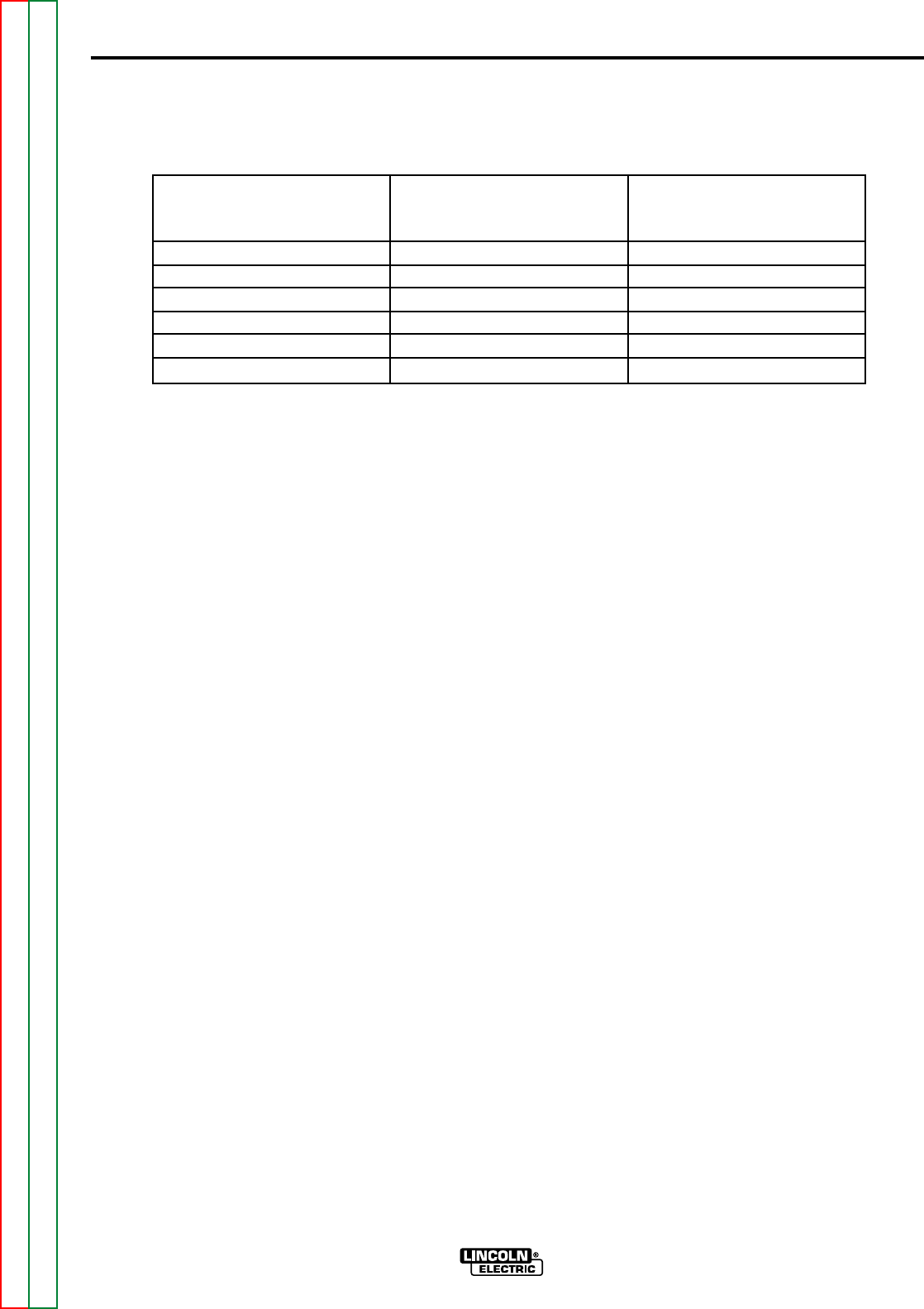
7. Measure the resistance across the
contacts. A resistance of less than
one ohm indicates that the con-
tacts are closed. An infinite resis-
tance indicates that the contacts
are open. Energize the 24VDC
power supply and measure the
resistance again. Compare to the
conditions given in Table F.2. If the
readings do not match the table,
the relay is faulty and should be
replaced.
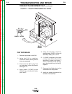
8. Repeat the above procedure for all
of the contacts.
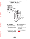
9. Re-install relay into the relay
board.
10. Install the screws that secure the
left side cover assembly.
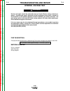
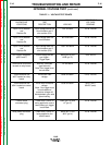
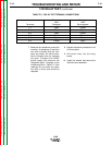
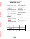
1CR RELAY TEST (continued)
TABLE F.2 – RELAY TEST TERMINAL CONNECTIONS
LN-8
Terminals Terminals
A&B A&B
Terminals Energized De-energized
7-1 Open Closed
7-4 Closed Open
8-2 Open Closed
8-5 Closed Open
9-3 Open Closed
9-6 Closed Open