


F-13
TROUBLESHOOTING AND REPAIR
F-13
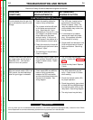
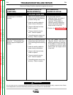
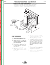
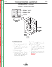
TEST PROCEDURE
1. Remove input power to the LN-8.
2. Using the 5/16 in. nutdriver,
remove the screws holding the left
side cover assembly.
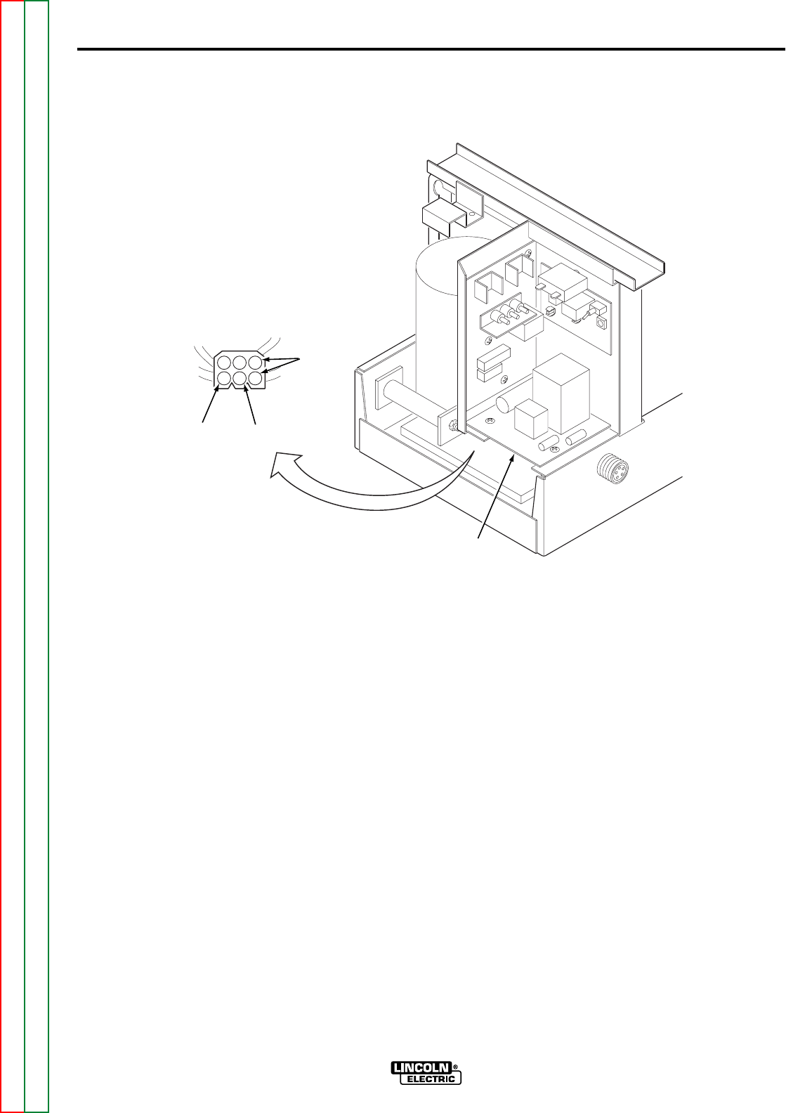
3. Disconnect the Molex plug from
the under-side of the relay board.
See Figure F.2.
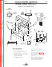
4. Apply power (115VAC) to the
black primary transformer leads,
pins 2 and 3.
5. Using the voltmeter, check for
approximately 24VAC at the red
secondary leads, pins 1 and 4.
6. If 115VAC is applied to the black
primary leads (2 and 3) and the
secondary voltage (red leads 1
and 4) is missing or low, the trig-
ger transformer may be faulty.
Replace.
7. Reconnect the Molex plug to the
underside of the relay board.
8. Install the screws that secure the
left side cover assembly.
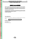
TRIGGER TRANSFORMER TEST (continued)
FIGURE F.2 – TRIGGER TRANSFORMER TEST POINTS
LN-8
Return to Section TOC Return to Section TOC Return to Section TOC Return to Section TOC
Return to Master TOC Return to Master TOC Return to Master TOC Return to Master TOC
654
321
BLACK
BLACK
RED
RELAY
BOARD