


Return to Section TOC Return to Section TOC Return to Section TOC Return to Section TOC
Return to Master TOC Return to Master TOC Return to Master TOC Return to Master TOC
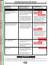
1. Check the Ground Lead
Protector (GLP). Reset if
necessary.
2. Check the circuit breaker. Reset
if necessary.
3. Make sure 115VAC is being
applied to the LN-8 at the input
receptacle. Pin “C” lead #31 and
pin “D” lead #32.
4. Check the 1/2 amp fuse located
on the relay board. Replace if
necessary.
5. If the LN-8 has a variable voltage
board and the power source is a
constant current supply, check to
make sure the switch on the vari-
able voltage board is in the “VV”
position.
6. If the switch on the variable
board is in the “VV” position,
make sure the power source is
set for an open circuit voltage of
30VDC or more.
F-4
TROUBLESHOOTING AND REPAIR
F-4
LN-8
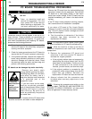
Observe all Safety Guidelines detailed throughout this manual
If for any reason you do not understand the test procedures or are unable to perform the tests/repairs safely, contact the Lincoln Electric
Service Department for technical troubleshooting assistance before you proceed. Call 1-800-833-9353.
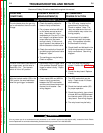
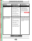
CAUTION
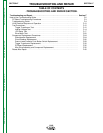
POSSIBLE AREAS OF
MISADJUSTMENT(S)
RECOMMENDED
COURSE OF ACTION
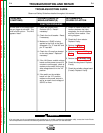
No wire feed or arc voltage when
the gun trigger is activated. The
drive rolls do not turn. The LN-8
appears “dead”.
1. Check for loose or faulty con-
nections between the input
receptacle, the circuit breaker,
and the 2 ohm resistor. See
wiring diagram.
2. Check the 2 ohm resistor.
Replace if faulty.
3. Perform the Trigger
Transformer Test.
4. Perform the Internal Voltage
Test.
5. Perform the 1CR Relay Test.
6. Check the relay board. Replace
if faulty.
7. Check the variable voltage board
(if used). Replace if faulty.
TROUBLESHOOTING GUIDE
PROBLEMS
(SYMPTOMS)
FUNCTION PROBLEMS