


Return to Section TOC Return to Section TOC Return to Section TOC Return to Section TOC
Return to Master TOC Return to Master TOC Return to Master TOC Return to Master TOC
F-15
TROUBLESHOOTING AND REPAIR
F-15
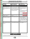
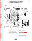
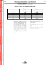
TEST DESCRIPTION
1. Remove input power to the LN-8.
2. Using the 5/16 in. nutdriver,
remove the screws from the left
side cover assembly.
3. Lift the left side cover.
4. Apply 115VAC to the input
receptacle at pins C and D.
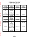
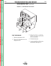
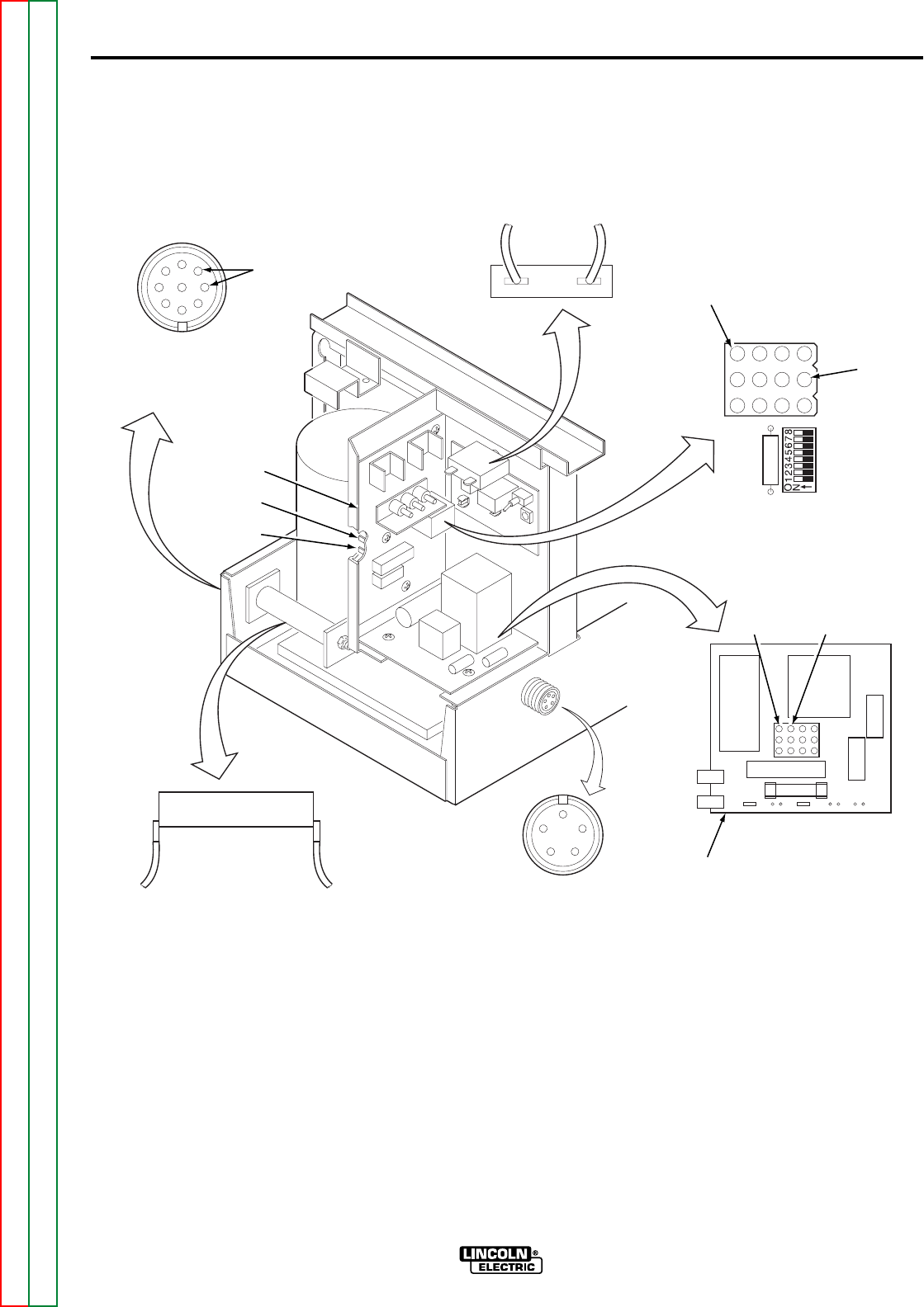
5. Using the voltmeter, carefully
test the voltages per Table F.1
at the test points shown in
Figure F.3.
6. When testing is complete,
install the screws that secure
the left side cover assembly.
LN-8
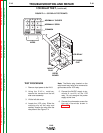
INTERNAL VOLTAGE TEST (continued)
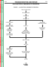
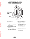
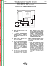
FIGURE F.3 – VOLTAGE TEST POINTS
32 32A
INPUT
CIRCUIT
BREAKER
CONTROL
BOARD
CONNECTOR
PLUG
PIN #12
(32A)
PIN #2
(7)
7 32A 525
(A)
RELAY
BOARD
627
626
PIN #1
(32A)
PIN #4
(531)
GUN TRIGGER
RECEPTACLE
A
BC
D
E
2 OHM
RESISTOR (R4)
31 531
CONTROL
BOARD
541
539
A
H
D
C
B
115 VAC
APPLIED
E
F
G
INPUT
RECEPTACLE