


Return to Section TOC Return to Section TOC Return to Section TOC Return to Section TOC
Return to Master TOC Return to Master TOC Return to Master TOC Return to Master TOC
F-6
TROUBLESHOOTING AND REPAIR
F-6
LN-8
If for any reason you do not understand the test procedures or are unable to perform the tests/repairs safely, contact the Lincoln Electric
Service Department for technical troubleshooting assistance before you proceed. Call 1-800-833-9353.
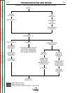
CAUTION
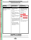
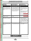
The circuit breaker (5 amp)
repeatedly trips when the gun trig-
ger is activated.
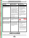
The circuit breaker (5 amp) trips
when power is applied to the LN-8.
Gun trigger is NOT activated.
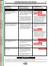
The 1/2 amp fuse on the relay
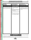
board repeatedly fails.
The drive motor thermostat “opens”
while welding.
1. Check or replace the gun trigger
and leads. Make sure the trigger
leads are not shorted to the elec-
trode or work cables.
2. Disconnect any accessory that
may be connected to terminals
#7 and #32A. See wiring dia-
gram. If the problem is resolved,
the accessory may be faulty.
1. Disconnect any kits or acces-
sories that may be incorporated
in the LN-8. Be sure to install
any necessary jumper plugs. If
problem is resolved the fault may
be in the disconnected kit.
1. Check to make sure the correct
input voltage (115VAC) is being
applied to the LN-8.
2. Very rapid and repetitive gun
triggering can possibly cause the
field fuse to fail.
1. Check for mechanical restric-
tions in the wire feeding path.
This condition could cause the
motor to overheat.
2. The electrode may be rusty or
dirty. Clean or replace.
1. Perform the Trigger
Transformer Test.
2. Perform the Drive Motor Test.
3. Remove the molex plug from the
relay board. If the circuit breaker
continues to trip, the control
board may be faulty. If the cir-
cuit breaker does not trip, the
relay board may be faulty.
1. Check the wiring harness leads
#32, #32A, #31, and #531 for
shorts or grounds. See wiring
diagram.
2. Perform the Trigger
Transformer Test.
3. Remove the molex plug from the
relay board. If the circuit breaker
continues to trip, the control
board may be faulty. If the cir-
cuit breaker does not trip, the
relay board may be faulty.
4. Perform the Drive Motor Test.
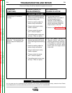
1. Perform the Drive Motor Test.
2. Perform the Trigger
Transformer Test.
2. The relay board may be faulty.
1. Perform the Drive Motor Test.
POSSIBLE AREAS OF
MISADJUSTMENT(S)
RECOMMENDED
COURSE OF ACTION
PROBLEMS
(SYMPTOMS)
Observe all Safety Guidelines detailed throughout this manual
FUNCTION PROBLEMS (Continued)