


F-27
TROUBLESHOOTING AND REPAIR
F-27
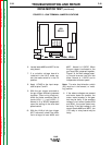
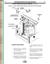
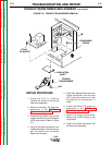
REPAIR PROCEDURE
1. Using the 5/16 in. nutdriver,
remove the screws from the left
side cover assembly.
2. Tag and remove the two connec-
tors from the back of the circuit
breaker. Refer to Figure F.8.
3. Using the 9/16 in. wrench, remove
the retaining nut that secures the
circuit breaker to the center panel
on the wire feeder. Remove the
circuit breaker from the wire
feeder.
4. Install the new circuit breaker
through the panel of the control
box. Secure the circuit breaker
with the retaining nut.
5. Install the connectors onto the
back of the circuit breaker at the
positions they were removed from.
6. Install the screws that secure the
left side cover assembly.
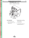
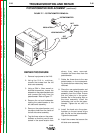
CIRCUIT BREAKER REPLACEMENT (continued)
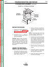
FIGURE F.8 – CIRCUIT BREAKER AND GROUND LEAD PROTECTOR REPLACEMENT
LN-8
Return to Section TOC Return to Section TOC Return to Section TOC Return to Section TOC
Return to Master TOC Return to Master TOC Return to Master TOC Return to Master TOC
CIRCUIT
BREAKER
SCREW
GROUND LEAD
PROTECTOR SWITCH
SWITCH
MOUNT
FLATWASHER
LOCKWASHER
NUT
RETAINING
NUT