


E-3
THEORY OF OPERATION
E-3
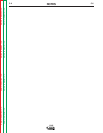
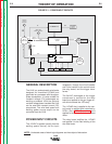
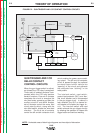
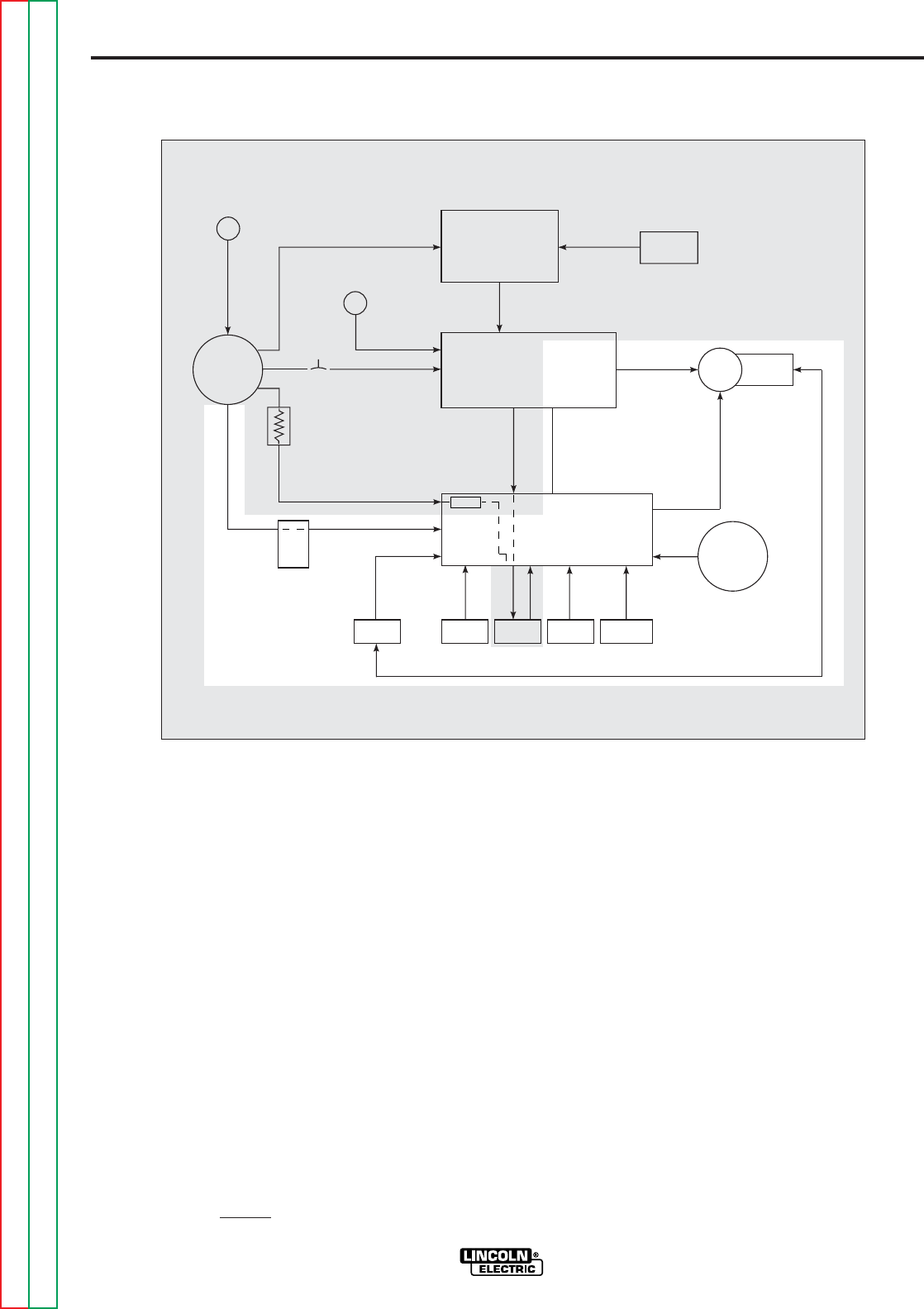
GUN TRIGGER AND 1CR
RELAY CONTACT
CONTROL CIRCUITS
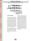
When the gun trigger switch is activat-
ed (closed) the 1CR relay is energized.
Three sets of isolated contacts incor-
porated within the 1CR relay perform
several functions. One set of contacts
completes the circuit to energize the
wire feed motor armature and also the
auxiliary circuit #7 and #32A. Another
set of contacts control the motor field
circuit polarity which, along with the
wire feed switch, dictate the wire feed
direction. The third set of contacts
control the #2 and #4 contactor circuit
which enables the power source weld-
ing output. The #2 and #4 contactor
circuit is passed through the optional
burnback board which delays the
“opening” of the circuit and prevents
the electrode from “sticking” in the
weld puddle.
The interlock switch, reed switch,
ground lead protector (GLP), and ther-
mal circuit breaker are all incorporated
in the gun trigger circuit. In case of a
fault condition, the GLP or thermal cir-
cuit breaker will disable the trigger cir-
cuit. The interlock switch and reed
switch enhance the gun trigger circuitry
by allowing the operator to release the
trigger button and continue welding.
FIGURE E.2 – GUN TRIGGER AND 1CR CONTACT CONTROL CIRCUITS
LN-8
REMOTE
OUTPUT
CONTROL
ELECTRODE
METER
SHUNT
WIRE
FEED
MOTOR
CIRCUIT
BREAKER
INPUT
RECEPTACLE
VARIABLE VOLTAGE
BOARD
CONTROL
BOARD
WIRE FEED
SPEED CONTROL
THERMAL
CIRCUIT
BREAKER
RELAY
BOARD
GLP
REED
SWITCH
TRIGGER
TRANS.
WIRE
FEED
SWITCH
INTERLOCK
SWITCH
FUSE
GUN
CABLE
RECEPTACLE
FIELD
ARMATURE
#3
2
A
OPTIONAL
BURNBACK
BOARD
CONTROL
#2
&
#4
C
O
N
T
A
C
T
O
R
#531
#31
2 OHMS
#32 #32A
#75
#76
#77
#21
#567
NOTE: Unshaded areas of block logic diagrams are the subject of discussion.
Return to Section TOC Return to Section TOC Return to Section TOC Return to Section TOC
Return to Master TOC Return to Master TOC Return to Master TOC Return to Master TOC