


Return to Section TOC Return to Section TOC Return to Section TOC Return to Section TOC
Return to Master TOC Return to Master TOC Return to Master TOC Return to Master TOC
F-36
TROUBLESHOOTING AND REPAIR
F-36
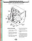
REPAIR PROCEDURE
1. Using the 5/16 in. nutdriver,
remove the screws from the left
side cover assembly.
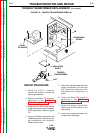
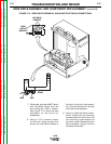
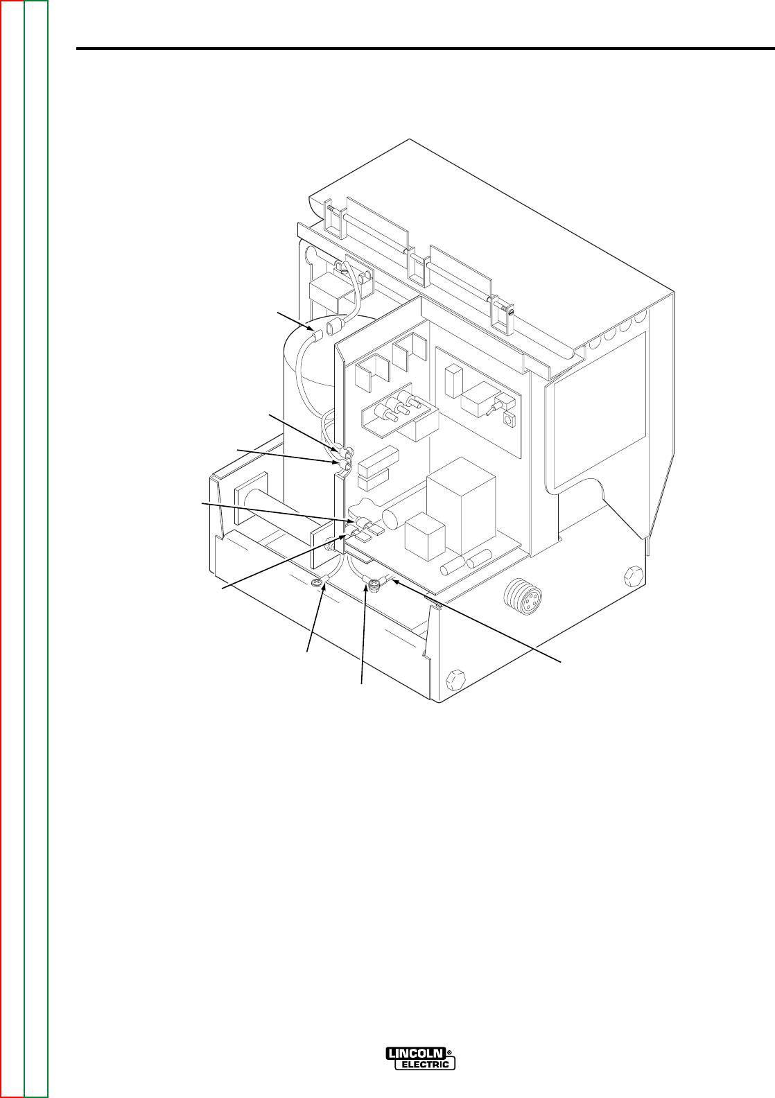
2. Disconnect drive motor leads #539
(blue) and #541 (black) from the
back of the Control PC board.
Refer to Figure F.11.
3. Disconnect drive motor leads #626
(red) and #627 (white) from the
side of the Relay PC board.
4. Using a Phillips screwdriver, dis-
connect the drive motor ground
lead (green) from the case.
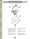
5. Separate ground lead protection
wire #525 (yellow) at the in-line
connector.
6. Remove the insulating tape from
wire #528 (yellow) and disconnect
it from the reed switch wire and
gun receptacle wire (#528, and
both blue leads) using a 11/32 in.
wrench and a Phillips screwdriver.
See the wiring diagram.
LN-8
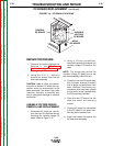
WIRE DRIVE ASSEMBLY AND COMPONENT REPLACEMENT (continued)
FIGURE F.11 – DRIVE MOTOR ELECTRICAL CONNECTIONS
YELLOW
(#525)
BLACK
(#541)
BLUE
(#539)
WHITE
(#627)
RED
(#626)
GREEN
(GROUND)
YELLOW
(#528)
BLUE (TWO)
(#528)