


A-4
A-4
INSTALLATION
Return to Section TOC Return to Section TOC Return to Section TOC Return to Section TOC
Return to Master TOC Return to Master TOC Return to Master TOC Return to Master TOC
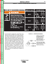
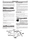
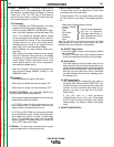
FIGURE A.2 — RECEPTACLE DIAGRAM
CONNECT TO A SYSTEM
GROUNDING WIRE. SEE
THE UNITED STATES
NATIONAL ELECTRICAL
CODE AND/OR LOCAL
CODES FOR OTHER
DETAILS AND MEANS FOR
PROPER GROUNDING.
CONNECT TO HOT WIRES
OF A THREE-WIRE, SINGLE
PHASE SYSTEM OR TO ONE
PHASE OF A TWO OR
THREE PHASE SYSTEM.
3. The Power MIG is shipped with a 10ft.(3.05m) input
cable and plug connected to the welder. Using the
instructions in Figure A.2, have a qualified electri-
cian connect the receptacle or cable to the input
power lines and the system ground per the U.S.
National Electrical Code and any applicable local
codes. See “Technical Specifications” at the begin-
ning of this chapter for proper wire sizes. For long
runs over 100ft. (30.48m), larger copper wires
should be used. Fuse the two hot lines with super
lag type fuses as shown in the following diagram.
The center contact in the receptacle is for the
grounding connection. A green wire in the input
cable connects this contact to the frame of the
welder. This ensures proper grounding of the
welder frame when the welder plug is inserted into
the receptacle.
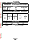
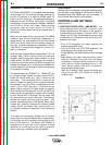
FIGURE A.1 — TRIPLE VOLTAGE MACHINE INPUT CONNECTIONS
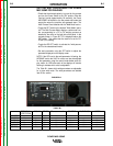
POWER MIG 350MP