


Return to Section TOC Return to Section TOC Return to Section TOC Return to Section TOC
Return to Master TOC Return to Master TOC Return to Master TOC Return to Master TOC
TROUBLESHOOTING & REPAIR
F-28 F-28
POWER MIG 350MP
WIRE DRIVE MOTOR AND TACHOMETER FEEDBACK TEST (continued)
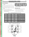
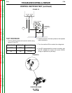
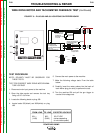
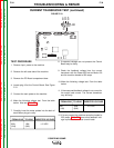
FIGURE F. 8 – PLUG J83 AND J84 LOCATIONS ON FEEDER BOARD
TEST PROCEDURE
NOTE: POLARITY MUST BE OBSERVED FOR
THESE TESTS.
TEST FOR CORRECT WIRE DRIVE MOTOR ARMA-
TURE VOLTAGE
1. Disconnect main input power to the machine.
2. Open the side panels and remove the tool tray
using a 5/16” nut Driver.
3. Locate the following leads on plug J83:
4. Locate leads 831(black) and 832(white) on plug
J83.
5. Connect the main power to the machine.
7. Make the following voltage tests. From the table
below.
8. Carefully insert the meter probes into the back of
each Molex plug pin cavity to perform the test.
9. Turn the machine ON and pull the gun trigger to
conduct this voltage test.
FROM LEAD TO LEAD EXPECTED VOLTAGE
831 + 832 - 2.5-27 VDC
(1J83) (2J83) (varies depending
on wire feed speed)
G3884
J83
J84
2J83
3J83
832
833
4J83
834
MOTOR -
GAS SOLENOID +
GAS SOLENOID -
1J83
831
MOTOR +
7J84
4J84
847
844
1J84
841
5VDC TACH SUPPLY
TACH SIGNAL
TACH COM
ACCESS THIS CONNECTOR
BY REMOVING THE WIRE
DRIVE ASSEMBLY
1
2
3
4
R
U
B
R
U
B
TACHMOTOR / GEARBOX
2.6 VDC @ 50 IN/MIN
27.4 VDC @ 700 IN/MIN
8 SECOND AVERAGE CURRENT
LIMIT = 3.5A
(LIMIT IS SOFTWARE SET)
MEASURE B TO U
120 Hz @ 50 IN/MIN
1.6 kHz@700 IN/MIN
LOCATED ON
CASE BACK
PWM CONTROLLED
6.5 VDC WHEN GAS
FLOWING COIL
MEASURES 21 OHMS
12 VDC COIL
1
2
BW
TOROID
TOROID
J83
J84
832
831
841
844
847