


TROUBLESHOOTING & REPAIR
F-52 F-52
POWER MIG 350MP
Return to Section TOC Return to Section TOC Return to Section TOC Return to Section TOC
Return to Master TOC Return to Master TOC Return to Master TOC Return to Master TOC
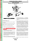
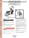
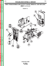
MAIN TRANSFORMER AND OUTPUT CHOKE REMOVAL AND REPLACE-
MENT (continued)
LEAD DISCONNECTION
8. Using a phillips head screwdriver, remove fan lead
X4 from fan relay terminal #1 and disconnect fan
lead X3 from its in-line connector at the fan motor.
Cut cable ties as needed pull the leads through the
baffles to clear them.
9. Using a 1/2” wrench, disconnect leads X1 and X2
from the output rectifier. Note the order of the fas-
teners for reassembly: bolt, flat washer, heavy
lead, terminal, lock washer, nut.
10. Disconnect leads X5 and X6 from the control recti-
fier (spade connectors).
11. Disconnect thermostat leads 502 and 503A from
their in-line connectors (right side of the machine).
12. Using a 3/8” nut driver, disconnect leads H2, H3,
and H5 from the reconnect panel terminals 2, 3,
and 5.
13. Using a 3/8” nut driver, disconnect leads H1 and H4
from the back of the line switch. Looking at the
back of the switch, H1 is at the bottom right and H4
is at the bottom left. Note that leads H1 and H4,
which go to the reconnect panel, attach at these
same terminals.
14. Using a 1/2” wrench and socket wrench, discon-
nect heavy lead B2 from the choke.
15. Using a 9/16” wrench and socket wrench, discon-
nect the heavy lead from the choke to the positive
output terminal. It is not necessary to remove any
other leads; screw the bolt with leads still attached
back into the positive output terminal until
reassembly.
MAIN TRANSFORMER AND CHOKE
ASSEMBLY REMOVAL
16. Using a 1/2” socket wrench, remove 4 nuts and
lock washers that hold the main transformer to the
machine base. Also remove the 4 in. bolts from
underneath.
17. Using a 5/16” nutdriver, remove the 2 screws that
hold the right and left transformer baffle in place (1
screw each). The center assembly and rear
assembly can now be lifted enough to allow the
main transformer and choke assembly to be
removed.
18. With the help of an assistant, lift the front of the
center assembly and slide the main transformer
and choke assembly out through the front of the
machine. Use care -- the assembly is very heavy.
REPLACEMENT PROCEDURE
For lead reassembly steps, also see the Wiring
Diagram.
1. With the help of an assistant, carefully slide the new
transformer/choke assembly into place. Attach it to
the machine base with 4 bolts, lock washers, and
nuts.
2. Attach the right and left transformer baffles to the
machine base (1 screw each side).
3. Connect the heavy lead from the top of the choke to
the positive output terminal.
4. Connect heavy lead B2 to the choke.
5. Connect leads H1 and H4 to the back of the line
switch. See disassembly step for details.
6. Connect leads H2, H3, and H5 to the reconnect
panel.
7. Connect thermostat leads 502 and 503A at their in-
line connectors (right side of the machine).
8. Connect leads X5 and X6 to the control rectifier
(spade connectors).
9. Connect leads X1 and X2 to the output rectifier.
Note the order of the fasteners: bolt, flat washer,
heavy lead, terminal, lock washer, nut.
10. Connect fan lead X4 to fan relay terminal 1 and fan
lead X3 at its in line connector at the fan motor.
11. Install the case front assembly. Connect plug J34
and mount the line switch.
12. Install new cable ties as needed.
13. Install the case sides and top.